适用于移动系统中的同步定位与建图硬件加速器
-
摘要:
同步定位与建图(SLAM)是机器智能化道路上的一个重要问题,在移动智能系统中更是扮演着重要角色。各种SLAM算法被提出解决该问题,但现存硬件平台在运行SLAM算法时难以满足移动系统对实时性和低功耗的要求。虽然设计专门的硬件来解决性能和功耗问题是十分有前景的,但是SLAM算法的多样性对这样的硬件设计提出了巨大的挑战。目前相关硬件工作都仅仅针对特定的SLAM算法或SLAM算法中特定阶段进行加速,却无法涵盖多类SLAM算法。
本文旨在设计出一种既能够满足实时性、低功耗要求,又能支持各种SLAM算法的通用SLAM硬件加速器。
为了实现这一目的,我们分析了几类有代表性的SLAM算法,发现SLAM算法中存在大量不同的运算模式且具有不规整的控制流。于是我们设计了一个包含矩阵、向量、标量三种不同粒度运算单元的加速器以覆盖SLAM算法多样的运算模式;同时设计了一种层次化的指令集,简化SLAM算法的控制流并支持更多SLAM算法。
我们以几种有代表性的SLAM算法作为测试用例,以Intel i7-3770和ARM Cortex A57作为比较对象进行实验。结果表明,相对于Intel处理器性能,本文加速器性能提升10.52倍,能耗减少112.62倍;相对于ARM处理器,本文加速器性能提升33.03倍,能耗减少62.64倍。
-
关键词:
- 硬件加速器 /
- 指令集 /
- 移动系统 /
- 同步定位与建图(SLAM)算法
Abstract:The emerging mobile robot industry has spurred a flurry of interest in solving the simultaneous localization and mapping (SLAM) problem. However, existing SLAM platforms have difficulty in meeting the real-time and low-power requirements imposed by mobile systems. Though specialized hardware is promising with regard to achieving high performance and lowering the power, designing an efficient accelerator for SLAM is severely hindered by a wide variety of SLAM algorithms. Based on our detailed analysis of representative SLAM algorithms, we observe that SLAM algorithms advance two challenges for designing efficient hardware accelerators: the large number of computational primitives and irregular control flows. To address these two challenges, we propose a hardware accelerator that features composable computation units classified as the matrix, vector, scalar, and control units. In addition, we design a hierarchical instruction set for coping with a broad range of SLAM algorithms with irregular control flows. Experimental results show that, compared against an Intel x86 processor, on average, our accelerator with the area of 7.41 mm2 achieves 10.52x and 112.62x better performance and energy savings, respectively, across different datasets. Compared against a more energy-efficient ARM Cortex processor, our accelerator still achieves 33.03x and 62.64x better performance and energy savings, respectively.
-
1. Introduction
Autonomous navigation in an unknown environment is a fundamental ability for mobile robots (e.g., unmanned ground vehicles, self-driving cars, and aerial robots). In the absence of an initial map of the unknown environment, the robot must simultaneously construct a map of the environment and keep track of its position on the map. This is the well-known simultaneous localization and mapping (SLAM[1]) problem. Conventionally, the SLAM problem can be approximately solved in acceptable time using statistical techniques such as particle filtering[2, 3], Kalman filters[4], and scan matching of range data[5] to process the data provided by a proper set of sensors (e.g., laser, sonar, radar, and camera). However, accurately solving SLAM in mobile robots with the limited computational ability and stringent power budget remains a challenging problem.
Currently, most of few accelerating solutions are proposed for hardware platforms such as GPUs[6-9] and FPGAs/FPGA+DSPs[10-12]. However, such platforms cannot fulfill the real-time processing requirements of mobile systems with a limited power budget. For desktop-level GPUs, efforts such as [6, 7] achieved around 10x performance (compared against CPUs), but the power consumption is nearly 100 watts. For embedded GPUs, Mardi et al.[8] achieved only 9.31x speedup on average on high-performance embedded GPUs, including NVIDIA Tegra and ARM Maili. Peng et al.[9] achieved only 1.41x–1.68x speedup on energy-efficient embedded GPUs which targets AI computing, including Jetson Xavier, Jetson TX2, and Jetson Nano. For FPGAs/FPGA+DSPs, despite the efficiency in performance and power, implementations are usually fixed to a certain algorithm and thus lack flexibility. Thus, efficient hardware for SLAM algorithms is still urged.
While specialized hardware promises to offer a real-time and low-power SLAM solution for mobile robots, several challenges exist in designing a highly efficient hardware accelerator for multiple SLAM algorithm variants, e.g., monocular SLAM[13, 14], stereo SLAM[15, 16], and RGB-D camera-based SLAM[17, 18]. First, unlike traditional accelerators that handle a limited number of computation patterns for limited algorithms, SLAM algorithms have significant diversity in their computations. For example, feature extraction in SLAM usually processes two-dimensional (2D) input images with massive matrix operations, while the optimization on the built map processes vertexes and edges that are complex data structures. Even these two specific functions involve many matrix/vector/scalar operations. Second, data access patterns vary drastically among different SLAM algorithms and even within a specific algorithm. Taking the data reuse distance in SLAM for example, input frames will be used only once but the extracted feature descriptors will be visited all the time in execution, not to mention the access patterns among different organized data. Third, very different from traditional accelerated algorithms, SLAM algorithms are data-control tightly coupled and contain many logic operations, which raises a challenge for designing accelerators with such complex control flows. In Section 4 of the real system analysis, the branch mispredicted instructions ratio in MonoSLAM is 3.17%, which is 3.36x/2.01x more than that in the convolutional neural network (CNN) training/testing phase, a recent common accelerated algorithm with ASIC (application specific integrated circuit)[19, 20]. Handling such control in an accelerator is critical. As a result, an ideal accelerator for SLAM should exploit varying computation and data access patterns with complex control for both high performance and energy efficiency.
In this paper, we propose a novel hardware accelerator to efficiently cope with a broad range of SLAM algorithms. We conduct a thorough analysis of various SLAM algorithms, and make several key observations, leading to our novel design solution. First, although different computation patterns exist, almost all operations can be classified into seven matrices, six vectors, and 12 scalar computation primitives. For example, Gaussian pyramid establishment in scale invariant feature transform algorithm (SIFT)[21] consists only of matrix convolution, matrix down-sampling, and matrix multiplication with scalar. Preconditioned conjugate gradient (PCG)[22] in optimization consists of vector multiplication and vector inner production. Thus, we implement a matrix processing unit (MPU), a vector processing unit (VPU), and a scalar processing unit (SPU) for the very few remaining operations to address the challenge of the variety of computation patterns. Second, data access patterns can be divided into two main categories: 2D data mainly for matrix operations and one-dimensional (1D) data for vector and scalar operations. Thus, we implement two types of on-chip buffers, 2D SRAM and 1D SRAM, to feed different processing units efficiently. Gaussian pyramid establishment only needs to access 2D SRAM for input and outputs, and PCG only needs to access vectors which are stored in 1D SRAM. Third, we propose a specially designed instruction set architecture (ISA) with the jump and condition branch instructions to well support complex control/data flows. Additionally, with the proposed ISA, future SLAM algorithms that contain the same patterns can be efficiently accelerated with the same ISA-based accelerator as well.
The key contributions of this paper are as follows.
● We propose a benchmark suite BenchSLAM, which is the basis for our later analysis, based on the principles of completeness, representativeness, and practicability.
● We conduct a thorough analysis of different SLAM algorithms in BenchSLAM to extract their computation and control flow behaviors, which provides a solid foundation for designing an efficient SLAM accelerator.
● We propose a SLAM accelerator built on matrix/vector/scalar processing units, a dedicated control unit, as well as an on-chip storage system, for efficiently coping with various SLAM tasks.
● We propose a hierarchical instruction set which not only copes with a broad range of SLAM algorithms with irregular control flows but also provides both flexibility and scalability in our accelerator for future SLAM algorithms.
● We show how to map algorithms to our accelerator and evaluate BenchSLAM in our accelerator. The experimental results show that our accelerator with the area of 7.41 mm2 achieves 10.52x and 112.62x better performance and energy savings over Intel Core i7-3770 processor respectively, and achieves 22.03x and 62.64x better performance and energy savings over ARM Cortex A57 processor respectively.
The remainder of this paper is organized as follows. Section 2 makes a brief introduction to SLAM algorithms, which can be divided into three categories: extended Kalman filtering (EKF) SLAM, particle filtering (PF) SLAM, and graph-based SLAM. Section 3 builds BenchSLAM, a benchmark containing mainstream SLAM algorithms, and extracts key operations of these SLAM algorithms. Section 4 conducts a detailed analysis of deploying BenchSLAM on a real system, including the performance and power behaviors, architectural bottlenecks, and the control flow behaviors. Section 5 illustrates the architecture of the proposed accelerator and its submodules. Section 6 introduces our proposed hierarchical instruction set which bridges the gap between the software/algorithm and hardware/scheduling. Section 7 elaborates how to map various SLAM algorithms to our accelerator. Section 8 evaluates the proposed accelerator against the baseline hardware. Section 9 lists some related work, including SLAM algorithms and hardware acceleration methods. Section 10 draws several conclusions.
2. SLAM Background
Solving the SLAM problem can be formulated as the estimation of a joint state of the robot's pose and the locations of map landmarks[1]. Mathematically, at time step k, the joint SLAM state vector is denoted as \left ( {\boldsymbol{x}}_{k},{\boldsymbol{m}}_{k} \right ) , where {\boldsymbol{x}}_{k} is the vector of the robot's pose and {\boldsymbol{m}}_{k} is the vector of landmarks. The basic idea of solving the SLAM problem is to estimate the posterior probability of the joint SLAM state vector based on the observations of the environment {\boldsymbol{o}}_{0:k} , the history of control inputs {\boldsymbol{u}}_{0:k} , and an arbitrarily selected initial position {\boldsymbol{x}}_{0} :
P\left ( {\boldsymbol{x}}_{k}, {\boldsymbol{m}}_{k} \mid {\boldsymbol{o}}_{0:k}, {\boldsymbol{u}}_{0:k}, {\boldsymbol{x}}_{0}\right ). (1) A large variety of solutions have already been used for solving the above equation, and they can be roughly divided into three categories from the perspective of computational paradigms[23]: EKF SLAM, PF SLAM, and graph-based SLAM.
The EKF SLAM employs the well-studied standard extended Kalman filtering techniques to approximate the joint posterior distribution of (1). Though EKF approaches are relatively easy to implement, they are computation- and memory-intensive as the size of joint covariance matrix increases quadratically with the number of landmarks. Also, since the Kalman filter works under a linear Gaussian assumption, the nonlinear motion and observation models in SLAM may easily lead to inconsistent and divergent solutions[24].
The PF SLAM relies on particle filters, which are sequential Monte Carlo methods using particle representation of probability densities[25], allowing for the direct representation of nonlinear models and non-Gaussian distribution. This is different from the EKF approaches that assume Gaussian distribution at every time step. Though the particle filtering approach has led to several important and famous algorithms such as FastSLAM[3], setting the proper number of particles remains a challenging problem[26]. Besides, the particle filtering approach may suffer from the inconsistency problem as well[27].
The graph-based SLAM addresses the SLAM problem via graph-based formulation[28]. A sparse graph, where the node corresponds to a robot position during mapping and the edge between two nodes corresponds to the spatial constraints between them, is constructed. Once the graph is constructed, it can be addressed by solving a large error minimization problem[29]. Due to the sparsity of the constructed graph, this approach can be solved efficiently with advanced optimization methods (e.g., sparse linear algebra libraries). However, the initial position can significantly affect the final result.
3. BenchSLAM Design
In this section, we introduce our proposed BenchSLAM, a benchmark suite containing several representative SLAM algorithms.
3.1 Design Objectives
We focus on three key objectives during the design of BenchSLAM.
● Completeness. The benchmark suite should cover existing SLAM algorithms as many as possible.
● Representativeness. The benchmark suite should include the most representative SLAM algorithms.
● Practicability. The studied algorithms should be practical for mobile robots with real-time and low-power requirements.
3.2 Benchmarks and Algorithmic Components
Based on the discussion in Section 2, to guarantee completeness, we choose SLAM solutions from three main SLAM categories: EKF SLAM, PF SLAM, and graph-based SLAM. To guarantee representativeness, we consider the most well-known approaches from each category. Also, due to the practicability requirement, we only consider algorithms that can be easily deployed on mobile robots. Eventually, four algorithms are considered in BenchSLAM: EKF SLAM[4], PF SLAM[3], RGB-D SLAM[18], and ORB (oriented FAST (features from accelerated segment test)[30] and rotated BRIEF (binary robust independent elementary features)[31]) SLAM[32], where both RGB-D SLAM and ORB SLAM are the most representative and practical graph-based SLAM algorithms. Note that we also notice SLAMBench[8], but it is a benchmark for only 3D scene understanding applications. Thus, we propose BenchSLAM instead in this paper for benchmarking various SLAM algorithms.
3.2.1 EKF/PF SLAM
The overall flow of EKF/PF SLAM is shown in Fig.1 as they share the same stages. Generally, EKF SLAM is composed of three steps: computing, prediction, and update.
In the computing step, true coordinates are obtained through motion modeling.
In the prediction step, the new robot state is predicted based on the last estimation and the control inputs.
In the update step, which may only happen under specific requirements, the observed range and bearing measurements are obtained and used for finding associated data, and then the state and covariance are updated.
3.2.2 RGB-D SLAM
RGB-D SLAM is designed for the RGB-D camera, and the most well-known RGB-D SLAM algorithm is from the Kinect platform[18]. The overall flow of RGB-D SLAM is shown in Fig.2[18], including the frontend for processing camera data to the geometric relationship (feature extraction, transformation validation, and transformation estimation), the backend for finding the maximum likelihood graph of robot trajectory and the landmarks geometric relationship (graph optimization), and final map generation.
![]() Figure 2. Overall flow of RGB-D SLAM[18].
Figure 2. Overall flow of RGB-D SLAM[18].Feature extraction is the first step of processing after a frame is received from an RGB-D camera. During this step, various kinds of features extraction algorithms, e.g., SIFT (Scale Invariant Feature Transform)[21], and SURF (Speeded up Robust Features)[33], can be applied to calculate features of selected key points on the current input frame.
In transformation estimation, the transformation information between two frames will be estimated based on matched pairs of key points, which are obtained by measuring the similarity (e.g., Euclidean distance or Hamming distance in their feature spaces) of two key points from each frame. The RANSAC (Random Sample Consensus) algorithm[34] is applied instead of ICP (Iterative Closest Point)[35-37] in [18] for fastness and robustness.
After that, in transformation validation, a beam-based environment measurement model (EMM) is used to verify the estimated transformation information since both RANSAC and ICP cannot avoid unsuccessful estimation especially when two frames have low overlap or few features.
Then in graph optimization, based on the graph obtained in the frontend, which contains the estimated transformation between different frames, i.e., sensor poses, backend processing computes the global consistent trajectory with maximum likelihood by optimizing the estimation errors. A widely-used framework, called g2o (General Graph Optimization)[38], is implemented to perform the minimization of a nonlinear error function.
The final map generation is a projection of the original points measurements with the optimized graph to form a point cloud representation[39] of the outside environment in the same coordinates.
3.2.3 ORB SLAM
ORB SLAM[32] is a binary invariant feature (e.g., 256-bit descriptor) built upon the FAST key-point detector and the BRIEF descriptor. It is widely used for object recognition, image stitching, visual mapping, etc.[40]. The essential ORB SLAM algorithm consists of three parallel tasks: tracking, local mapping, and loop closing, as shown in Fig.3[32].
![]() Figure 3. Overall flow of ORB SLAM[32].
Figure 3. Overall flow of ORB SLAM[32].The tracking task localizes the pose of the camera with every received frame and determines when to insert a keyframe. Initially, the ORB features are extracted from the input frame. Then, an initial feature matching with the last frame is conducted. If successful, the camera pose is estimated from the previous frame; otherwise, global relocalization is performed for predicting the camera pose. Once we have an initial estimation of the camera pose and a set of feature matches, a local map can be projected into the frame and more map points are searched in the frame. With found map points, the camera pose is optimized again. Finally, the task determines whether the current frame should be inserted as a keyframe.
The local mapping task is in charge of processing new keyframes and optimizing their local neighborhood. In more detail, the new keyframe is inserted as a node into the so-called covisibility graph. The local BA (bundle adjustment) optimizes the keyframe and all its neighbors in the covisibility graph. The map points seen by these keyframes are optimized as well. The local mapping also removes redundant keyframes.
The loop closing task is designed to maintain the global consistency of the constructed map. This task can be further divided into two steps: loop detection and loop correction. In loop detection, once a loop is detected with the current keyframe, a similarity transformation is computed to obtain the accumulated error in the loop. Then, in loop correction, the duplicate points in the loop are fused, and the optimization over the essential graph (i.e., a sparse graph generated from the original covisibility graph) is performed to guarantee consistency.
3.2.4 Algorithmic Components
All the key operations in the above algorithms can be grouped into three categories: matrix, vector, and scalar operations.
● The most representative matrix operations in BenchSLAM include the convolution operation in the RGB-D SLAM and the singular value decomposition (SVD) in the ORB SLAM.
● Typical vector operations are the key-points Euclidean distance calculation and the coordinate projection in the RGB-D SLAM and the ORB SLAM, respectively.
● The scalar operations are also very common for all benchmarks, for example, range and bearing computing in the EKF SLAM, particles sampling in the PF SLAM, distance ranking in the RGB-D SLAM, and similarity evaluation in the ORB SLAM.
Therefore, an ideal SLAM accelerator should be able to efficiently process various matrix, vector, and scalar operations to guarantee high energy efficiency.
4. Real System Analysis
In this section, we conduct a detailed analysis on a real system. First, we introduce the evaluated platform and tools. Then, we analyze the performance and power behaviors of BenchSLAM. We also evaluate the control flow behaviors.
4.1 Platform and Tools
All the experiments are conducted on a 4-core Intel Core i7-3770 processor. Multiple analysis tools are used throughout to study BenchSLAM from various aspects. First to investigate the performance and power bottlenecks, the performance application programming interface (PAPI)[41] is employed to collect related performance counters. Second, to investigate the control flow behavior, the Intel Pin[42] is used for dynamic instrumentation.
4.2 Performance and Power Analysis
To identify both the computational and power bottlenecks of BenchSLAM, we profile the execution of BenchSLAM with PAPI.
On the one hand, for different SLAM algorithms, the distribution of execution time in their algorithm stages varies greatly. In Fig.4(a), for the EKF SLAM, most of the time is spent in the prediction and computing stages. However, for the PF SLAM, the update stage consumes 66.5% of the total time. For the RGB-D SLAM, the frontend (including feature extraction, matching, and RANSAC) dominates the entire execution time (i.e., 93.5% in RGB-D SIFT and 98.4% in RGB-D SURF). For the ORB SLAM, as the loop closing is not frequently invoked, the other two tasks (tracking and local mapping) cost 99.5% of the execution time.
On the other hand, the power consumption does not correlate with the execution time. In Fig.4(b), for EKF, the power consumption of the update stage is higher than that of the other two stages, though the update stage consumes only 8.1% of the total time. The observation is also validated by the power consumption of RGB-D SURF, where the power of the g2o stage is higher than that of the other stages, where the execution time is only 1.6% of the total time. Thus, to improve both performance and power efficiency, almost all stages of SLAM algorithms need to be well addressed. Furthermore, considering the significant diversity of the different stages in various algorithms, it is unwise to have the intuitive solution of combining the corresponding fixed-function hardware, which not only is costly but also has strictly limited functionality.
In general, according to above observations (shown in Fig.4), we have proved the inhomogeneity of performance and power consumption across various SLAM algorithms. Therefore, in terms of building a SLAM accelerator, it is inefficient to combine the corresponding fixed-function ASICs. For the combination method, each ASIC of the SLAM accelerator only processes the specific stages in SLAM algorithms, causing the low utilization and poor generalization of the whole hardware.
Moreover, an interesting observation is that all performance and power bottlenecks are dominated by matrix/vector operations. For example, in the EKF SLAM, most operations are basic matrix operations (matrix/vector multiplication and matrix/vector addition). In the feature extraction phase of RGB-D SLAM, the convolution and pooling operations are the most time-critical. As a result, it is necessary to accelerate a broad range of matrix and vector operations to improve the energy efficiency of SLAM algorithms.
4.3 Architectural Bottlenecks
We also identify the architectural bottlenecks of BenchSLAM to investigate the potential improvements derived from using an optimized general-purpose architecture, which is an intuitive option for SLAM acceleration. Fig.5 shows the CPI (cycle per instruction) stack[43] of different SLAM algorithms. The base CPI is 0.25 for different algorithms as we are evaluating on a CPU with an issue width of 4 and the resultant CPI varies significantly. In this case, even adopting a general-purpose processor and assuming unlimited cache sizes and perfect branch predictors, the potential speedup is limited for these algorithms. For example, the EKF can achieve 5.8 x speedup, while the RGB-D SIFT only achieves a 2.6 x speedup. Therefore, it can be concluded that a customized architecture rather than an optimized general-purpose architecture is required for extremely high efficiency.
4.4 Control Flow Analysis
The complicated control flow behaviors in SLAM algorithms significantly hinder the exploitation of hardware parallelism. To gain more insights into the control flow behaviors, we compare the branch misprediction of BenchSLAM, neural network algorithms (which are built with relatively regular and simple control flows, and have received increasing attention recently[19, 20]), and several general-purpose applications from SPEC CPU 2006, including gcc and libquantum with a large number of hard-to-predict branches[44]. In Fig.6, we report the ratios of branch misprediction which indicate the frequency of irregular jumps in algorithms, i.e., the complexity of control flow, while the regular branch structure can still be easily handled by the hardware design. We can observe that the misprediction ratios in SLAM algorithms are higher than those in neural network algorithms (e.g., 15.6% in EKF vs 1.6% in CNN test). Even compared against general-purpose applications, the misprediction ratios are higher, e.g., 3% in ORB SLAM vs 1% in gcc.
The above observations demonstrate that SLAM algorithms have relatively complicated control flow behaviors. Thus, light control units in traditional hardware accelerators (e.g., the control units in CNN processors[19, 20] for neural network algorithms) are not able to process the control flows in SLAM algorithms. On the other hand, heavy control units (such as branch predictors in general purpose processors) are inappropriate for processing control flows in SLAM algorithms because of stringent power and performance constraints. In other words, a dedicated hardware unit specifically targeting the control flows in SLAM algorithms advances a great challenge during the accelerator design.
5. Accelerator Design
Fig.7 illustrates the overall architecture of the proposed accelerator. It mainly consists of a matrix processing unit (MPU), a vector processing unit (VPU), a scalar processing unit (SPU), multiple data/instruction SRAMs, and a control unit (CU). The MPU, VPU, and SPU are used for the computation of matrix, vector, and scalar operations, respectively. The input data of these processing units are accessed from the data SRAMs through DMA (direct memory access). In particular, the MPU requires two SRAMs to provide sufficient data from both the horizontal and vertical directions. The CU controls the execution of the entire accelerator with compiler-generated instructions stored in the instruction SRAM.
5.1 Matrix Processing Unit
The MPU is in charge of processing a large variety of dominant matrix operations (e.g., matrix transposition, matrix multiplication, singular value decomposition, QR decomposition, and convolution operation). Fig.8(a) shows the detailed architecture of the MPU, which can be further decomposed into a 2D mesh of P_{x} \times P_{y} matrix processing elements (MPEs) and a buffer controller. All the MPEs are organized as a 2D mesh with the adjacent-interconnection structure and controlled by the central buffer controller. The buffer controller supplies data to the rightmost column and the bottom row of the MPE array, i.e., Input-H and Input-V in Fig.8(a), respectively. The buffer controller can also directly provide input data (i.e., input in Fig.8) to all the MPEs. In addition, the output data (i.e., output in Fig.8) computed by all the MPEs can be collected by the buffer controller for storing in the SRAMs.
Fig.8(b) shows the architecture of each MPE. The central component of the MPE is the functional unit (FU) that is capable of completing basic operations (e.g., floating-point addition/multiplication and floating-point/fixed-point conversion). The FU can receive data from its right and bottom neighbors (Input-H and Input-V, respectively) as an input. In addition, the FU may also use previous data stored in its internal register as one of the inputs. This is simply because multiplication-accumulation is commonly used in arithmetic operations such as vector inner production and matrix multiplication. Thus each MPE can be activated in a multiplication-accumulation mode. Another source of inputs is the data directly accessed from the outside SRAM (i.e., input). The input data from the outside SRAM also enter two FIFOs (i.e., FIFO-V and FIFO-H) for providing data to the top and left MPEs (Data-V and Data-H, respectively). Once the FU finishes the computation, the MPE outputs the result from the FU or directly from the internal register. The opcode from the CU selects the input data and decides which concrete operation will be performed.
The key reasons for the adjacent-interconnection structure in 2D MPE mesh (allowing each MPE to access data from its neighboring MPEs and SRAMs) are: 1) to support the accumulation of intermediate results among MPEs for operations such as inner production, 2) to elevate the data utility by leveraging the data locality and reuse for operations such as convolution, and 3) to remain an efficient hardware implementation by avoiding full connections among all MPEs.
5.2 Vector Processing Unit
The VPU processes the vector operations, such as vector addition/multiplication/accumulation, in BenchSLAM. The organization of the VPU is shown in Fig.9(a). It contains P_{z} vector processing elements (VPEs). For each VPE, there are three main input sources: 1) data in the outside SRAM, 2) outputs of the MPU, and 3) outputs of the right-side neighboring VPE (Data-H in Fig.9(b)). The concrete inputs are determined by the opcode from the CU. The key reason to have multiple input sources is that VPU can efficiently support independent operations such as dot production (independent inputs for each VPE) and dependent operations such as inner production (multiplication-accumulation mode and inputs from the neighboring VPE and the internal register). Especially for the latter inter-PE data movements, the VPU can fetch data from the neighbor PEs and thus eliminate data accesses from SRAM in some operations, which is different from commonly used vector units in parallel machines.
The detailed architecture of a VPE is shown in Fig.9(b). Two input multiplexers (MUX) are used for selecting inputs for the functional unit. The result of the functional unit will be directly treated as the output or stored into the internal register. Similar to the MPE, the output multiplexer determines whether the output of the VPE is from the functional unit or the internal register.
5.3 Scalar Processing Unit
The SPU is required for processing relatively general scalar operations in BenchSLAM. The detailed architecture of SPU is similar to that of one VPE. The major difference is that the functional unit of the SPU is more versatile than that of the VPE, as more operations (such as sqrt, sin, cos, and random number generation) are supported by the SPU.
5.4 Control Unit
The control unit schedules and configures the entire hardware accelerator with user-provided instructions. All those VLIW (very long instruction word)-like instructions are first stored in the instruction SRAM and then processed by the control unit as shown in Fig.10. More specifically, the CU fetches an instruction according to the program counter (PC), and then different parts of the instruction are sent to the corresponding decoders (including the macro, matrix, vector, scalar, and data decoders). The decoders will generate control signals for the corresponding processing unit except for the macro decoder, which will generate control signals for all processing units. The CU supports direct jump and indirect jump instructions with the address stored in the operand fields of the instructions and internal controller registers, respectively, allowing the handling of complicated control flows in SLAM algorithms.
5.5 Data SRAMs
In addition to the instruction SRAM, two data SRAMs are provided for storing inputs and outputs of all the processing units (MPU, VPU, and SPU) to avoid data conflicts. In particular, the input data of the MPU are first read into two buffers (the row buffer and the column buffer) for supplying data to the bottom and the right boundaries of the MPU, respectively. The roles of the two SRAMs can be exchanged only after a computation stage is totally finished, and the previous output data become the input for later processing, such as the Gaussian blur operation after the frame is resized in SIFT. Additionally, data are stored based on their different organization, such as 2D matrix data (2D SRAM), 1D vector data, and scalar data (1D SRAM), to simplify the access patterns. Thus, the MPU requires massive 2D SRAM and a few 1D SRAM accesses as most matrix operations are mapped to the MPU, while the VPU requires both 2D SRAM and 1D SRAM accesses, and the SPU can only access 1D SRAM.
6. Instruction Set Design
In this section, we introduce our proposed hierarchical instruction set for bridging the gap between software/algorithm and hardware/scheduling.
6.1 Design Objectives and Components
There are three design principles in our instruction set.
● Effectiveness and User-Friendliness. The instruction set should balance the trade-off between programmability and efficiency.
● Completeness. The instruction set should be complete for programming existing SLAM algorithms.
● Scalability. The instruction set should be compatible with future potential SLAM algorithms.
Following these three principles, we design six groups of instructions—data, control, macro, matrix, vector, and scalar instructions, which are organized as the VLIW style to have a flexible control flow.
● We use five data instructions for data transferring among DRAM, SRAM, and internal buffers.
● Based on the algorithmic components analyzed in Subsection 3.2.4, we design 21 macro instructions dedicated to performing those algorithmic components with both high performance and energy efficiency.
● We also provide two control instructions, seven matrix instructions, six vector instructions, and 12 scalar instructions for the remaining computation, delivering flexibility and scalability for future SLAM algorithms.
The reason behind our instruction set design is threefold. First, with the higher-level functionality provided by macro instructions, programmers are expected to easily build their SLAM algorithms using mostly common algorithmic components. Second, other non-macro instructions provide the potential to perform other computations in both existing and future SLAM algorithms using our built compiler. Note that low-level functional instructions, i.e., non-macro instructions, can also perform the same functionality as macro instructions. Third, macro instructions also release the heavy burden on the compiler in traditional VLIW processors for parallel-executing programs with high efficiency. Therefore, our instruction set has hierarchical instructions to guarantee effectiveness, user-friendliness, completeness, and scalability.
Moreover, we have discussed irregular control flows in Subsection 4.4, which could be solved by the hierarchical instruction set, together with the control flow unit (introduced in Subsection 5.4) which acts as the specialized decoder matching the hierarchical instruction set. More specifically, high-level functional instructions (macro instructions) deal with complex (and common) computational patterns in SLAM algorithms, which simplifies the instruction flow and significantly reduces branches/jumps. For example, the EKF SLAM algorithm is executed in an iterative mode. In each iteration, robots receive motion control signals and observe various landmarks. However, it is uncertain about how many landmarks are observed in the current iteration and which of them have been observed before (i.e., the observed landmarks need to be updated). Therefore, there are computational imbalances in processing related vectors and submatrices among iterations. As a result, such uncertainty and imbalance would cause irregular control flows. Moreover, there are many small-scale vector and matrix operations as the dimensions of the pose state and the landmark state are generally small, e.g., three dimensions for the pose state in a 2D scene. These small operations, implemented by loops, would bring intensive branches/jumps, which may exhaust history entries of the branch predictor in CPUs and cause a high-branch misprediction ratio. We propose macro instructions to hide the uncertainty in control flows by aggregating multiple small-scale operations into monolithic matrix operations and making the uncertain number of landmarks (to be updated) be a configurable instruction field. Therefore, intensive branches/jumps in small operations are eliminated at source, and mispredictions could be reduced in algorithm implementations. Regular operations (e.g., CONV) in SLAM algorithms also benefit from this method, and thus branch mispredictions could be reduced further.
Table 1 lists a subset of the proposed instruction set as illustrative examples. The data instructions can be roughly grouped into three types: 1) LD/ST (load/store) for data transferring between SRAM and DRAM, 2) MOV (move) for data transferring between SRAMs, and 3) RD/WR (read/write) for data transferring between SRAM and internal buffers. The control instructions contain CB (condition branch) and JUMP (direct/indirect jump). The computational instructions include the macro, matrix, vector, and scalar instructions. The macro instructions are designed for relatively complicated operations such as convolution (CONV), pooling (POOL), and image accumulation (IMGACC). The matrix instructions include matrix-matrix, matrix-vector, matrix-scalar, and vector-vector operations, while the vector instructions only include vector-vector and vector-scalar operations. The scalar instructions only contain scalar-scalar operations. The choice of different instructions is left for an assembler.
Table 1. Subset of Proposed Instruction SetInstruction Type Opcode Note Data LD/ST SRAM \leftrightarrow DRAM MOV SRAM \leftrightarrow SRAM RD/WR SRAM \leftrightarrow buffers Control CB Condition branch JUMP Direct/indirect jump Macro CONV Convolution operation POOL Pooling operation IMGACC Image accumulation operation BOX Image box filtering operation LOCAL EXTREMA Local extrema operation COUNTCMP Compare with counter operation Matrix MMmM/ MMaM on-MPU-matrix-mult/
add-matrix operationMMmV on-MPU-matrix-mult-vector operation MMmS/ MMaS on-MPU-matrix-mult/
add-scalar operationMVmV/ MVoV on-MPU-vector-mult/outer product-vector operation Vector VVmV/ VVaV on-VPU-vector-mult/
add-vector operationScalar SQRT on-SPU-scalar-square-root operation RANDOM on-SPU-random-generate-scalar operation 6.2 Driving Examples
We introduce several important computing instructions as driving examples, including CONV for macro instructions, MMmV (on-MPU-matrix-multiply-vector), MMmM (on-MPU-matrix-multiply-matrix), MVmV (on-MPU-vector-multiply-vector) for matrix instructions, and VVmV (on-VPU-vector-multiply-vector) for vector instructions.
6.2.1 CONV
In Fig.11(a), we show the scheduling of the CONV instruction in the accelerator, which finishes a 2D convolution operation on an input matrix/image to construct an output matrix/image (a common operation in the feature extraction stage of SLAM algorithms), using 3\times 3 convolution on a 3\times 3 MPU for a clearer illustration. The input/output image will be split into chunks (i.e., pixel submatrices of the input/output image). The output image will be computed according to chunks and related kernels (i.e., parameters shared among input chunks), and each chunk will be loaded into on-chip 2D SRAM. In the CONV computation, the process of kernels sliding over an input image is split into the sliding over chunks (green and blue data in the row/column buffer shown in Fig.11) for parallelism. In each sliding step for one kernel, there is an element-wise multiplication between this kernel and an equal-size pixel submatrix of the chunk, and the sum of these intermediates yields an output pixel. Each MPE works on a single output pixel on the output image and changes to another output pixel in the same chunk until the current pixel is finished. The MPU processes 3\times 3 output pixels concurrently (i.e., the 3\times 3 green square on the output image in Fig.11). While computing a row in convolution, the input data from the column buffer will be passed from right MPEs to left MPEs (also buffered in MPEs); while computing the next row, the input data from the row buffer will be passed from bottom MPEs to upper MPEs.
To be clear about such inter-MPE data movements and reuses, we show the input data for four out of nine MPEs in the above example cycle by cycle in Fig.11(b). At the very first cycle, every MPE needs to fetch their input data from the outside SRAM and multiplies with the same convolutional kernel value ( K_{00} ). In the next two cycles, {\rm{MPE}}_{00} and {\rm{MPE}}_{10} can reuse the input data from {\rm{MPE}}_{01} (i.e., P_{01} , P_{02} ) and {\rm{MPE}}_{11} (i.e., P_{11} , P_{12} ), respectively, as indicated in blue in Fig.11(b). Then all MPEs will start new rows. Thus bottom-up data movements are activated as bottom MPEs just use and buffer such data (indicated in green). Repeating such inter-MPE data movement patterns, the 2D convolution of nine output pixels can be finished in nine cycles, and then all the pixels in the chunk and the whole output image.
We provide massive macro instructions such as CONV for high efficiency, even though the functionality of macro instructions can also be achieved using the provided matrix, vector, scalar, data, and control instructions. In Fig.12, we present the computation part of the assemble code for the convolution operation using non-macro instructions (the vector field is not used in this fragment) as well, which is scheduled in the same efficient flow as CONV. We can observe that data cannot be fully reused between different blocks, leading to costly data movements. In addition, explicit control instructions (e.g., CB and JUMP) used to implement loops may cause control flow issues, such as branch misprediction. Together with the synchronization between different fields of VLIW instructions, which are used for eliminating data conflicts, the non-macro code is not so efficient as the macro one in terms of performance and energy. Furthermore, even with the extra cost of the macro decoder, the CU only takes 3.10% of the area of the entire implemented accelerator.
6.2.2 MMmV
In Fig.13, we show the scheduling of MMmV, which finishes the matrix-vector multiplication on a 3\times 3 MPU example. Each MPE calculates one output data in the output vector by multiplying a row of the matrix with the input vector, and it will not move to another output until the current one is finished. During the process of MMmV, the MPEs concurrently work in a pipelined multiplication-accumulation mode and accumulate the multiplication results in their inside registers; thus for an input vector of length N , it will take N+1 cycles to calculate nine data of the output vector in this 3\times 3 MPU example.
6.2.3 MMmM
In Fig.14, we show the scheduling of MMmM, which operates the matrix-matrix multiplication on a 3\times 3 MPU example. Similar to MMmV, each MPE also calculates an output but here in the output matrix, and will insist on computing the current output until it is finished. For the case of multiplying matrix {\boldsymbol{A}}\left( m \times n \right) with matrix {\boldsymbol{B}}\left( n \times k \right) , three rows in {\boldsymbol{A}} and three columns in {\boldsymbol{B}} are fed into the MPU sequentially, while the MPEs in the same row share a row from {\boldsymbol{A}} , and the MPEs in the same column share a column from {\boldsymbol{B}} , as shown in Fig.14. Thus, nine outputs in the output matrix {\boldsymbol{C}}\left( m \times k \right) can be computed in n+1 cycles as the MPEs concurrently work in a pipelined multiplication-accumulation mode.
6.2.4 MVmV
In Fig.15, we show the scheduling of MVmV, which computes the vector-vector multiplication on MPU. An intuitive scheduling is mapping this computation to the VPU instead of the MPU. However, there also exists the case where the vectors are extremely long; thus, mapping on the VPU can be time-consuming. We provide the solution that maps such operations on the MPU to leverage the parallelism of MPEs (e.g., vector dot production operation and vector addition operation). With P_{x} \times P_{y} MPEs in the MPU, it can finish the multiplication of P_{x} \times P_{y} pairs of inputs and accumulate results into inside registers in each cycle (Fig.15(a)). After all inputs are fed into the MPU, P_{x} \times P_{y} accumulated partial productions are maintained in the P_{x} \times P_{y} MPEs (Fig.15(b)). The final result is obtained by adding all the P_{x} \times P_{y} intermediate results. Thus, the MPU is activated in a propagating-accumulation-summation mode where the MPEs are activated in row/column from the right/bottom to left/top sequentially to add inputs from the right/bottom and pass results to left/top (Fig.15(c) and Fig.15(d), respectively). Then the final result is collected from the top-left-most MPE.
![]() Figure 15. MVmV: the vector-vector multiplication on MPU. (a) Multiplication of P_{x} \times P_{y} pairs of inputs. (b) Accumulated partial productions in each MPE ( P_{x} \times P_{y} MPEs in total). (c) Propagating accumulation-summation from right to left in each MPE row. (d) Propagating accumulation-summation (Acc-Sum) from bottom to top in the left-most MPE column and outputting the final result from the top-left-most MPE.
Figure 15. MVmV: the vector-vector multiplication on MPU. (a) Multiplication of P_{x} \times P_{y} pairs of inputs. (b) Accumulated partial productions in each MPE ( P_{x} \times P_{y} MPEs in total). (c) Propagating accumulation-summation from right to left in each MPE row. (d) Propagating accumulation-summation (Acc-Sum) from bottom to top in the left-most MPE column and outputting the final result from the top-left-most MPE.6.2.5 VVmV
In Fig.16, we show the scheduling of VVmV, which computes the vector-vector multiplication on the VPU. Commonly, vector operations (e.g., vector multiplication and vector dot multiplication/addition/comparison) are mapped on the VPU. Similar to MVmV, each VPE performs the multiplication of a pair of inputs and accumulates the result into its inside register, and thus P_{z} intermediate results in total for the VPU. After all data in the input vectors are visited, the VPU works in a similar propagating-accumulation-summation mode as the MPU for MVmV except that only one direction propagation exists to add all P_{z} intermediate results. Then the final result is collected from the left-most VPE.
7. Algorithm Mapping
In this section, we elaborate on how to map various SLAM algorithms to our accelerator. Due to the page limit, we only introduce the mapping process of most representative algorithms (or phases) in BenchSLAM. Thus we select SIFT and g2o as driving examples as they are representatives of the frontend and the backend in graph-based SLAMs, respectively. Note that for all the processing algorithms, we build a simple compiler that can be used to generate instructions to reduce the heavy burden of programming sophisticated SLAM algorithms.
7.1 Feature Extraction: SIFT
As stated in Subsection 3.2.2, the SIFT algorithm is one of the key operations in RGB-D SLAM. However, it is nontrivial to map the entire SIFT algorithm to our accelerator, because it requires all types of computational instructions, including macro, matrix, vector, and scalar instructions.
Fig.17 shows the mapping process of the SIFT algorithm. The original image is first smoothed and reduced with the Gaussian pyramid, which can be decomposed into multiple CONV and POOL macro instructions. Then, the DoG (difference of Gaussian), which is employed to detect features, can be obtained by conducting matrix subtraction operations on different octaves of the image in the Gaussian pyramid. Once the DoG is found, the local extrema are searched on the image using a specially designed macro instruction, i.e., LOCAL EXTREMA. This is achieved by comparing a pixel with its neighboring pixels within one scale and across different scales as well. The local extrema are further filtered for determining the final keypoints. This process consists of numerous vector and scalar operations, e.g., vector inner production and matrix determinant/trace. Finally, the keypoint descriptor is created by computing multiple histograms on the neighboring points of the keypoint. This process also consists of multiple vector and scalar operations. In more detail, the computation of the histogram is achieved by using the macro instruction HIST which consists of vector operations of comparison and counting. The rotation of the neighbor pixel area is achieved by matrix-vector multiplication operations. Several transcendental functions such as exponential operation are computed by the SPU.
7.2 Graph Optimization: g2o
The g2o[38], a nonlinear graph optimization framework with least squares, is one of the bases of the graph-based SLAM (including RGB-D SLAM and ORB SLAM). In contrast to the SIFT algorithm, most operations in the g2o are matrix and vector operations.
Fig.18 shows the mapping process of the g2o algorithm. Given two poses {{i}} , {{j}} (i.e., two nodes in the pose graph) and their constraint (i.e., the edge between these two nodes), a user-defined error function and the corresponding Jacobian are first computed with matrix/vector operations such as matrix multiplication and vector MAC (multiply and accumulate operation). Then, a linear system is constructed to minimize the objective function. This is achieved by using multiple matrix/vector multiplication. To solve the linear system, an efficient linear solver, the preconditioned conjugate gradient (PCG)[45], is employed and PCG is performed by the macro instruction PCG, which can also be decomposed into matrix/vector multiplication operations. Finally, the poses are optimized and updated with vector MAC.
8. Experiments
8.1 Experimental Methodology
8.1.1 Tools
We implement the hardware accelerator with Verilog RTL, synthesize it with Synopsys Design Compiler, and perform the layout with IC Compiler. The power consumption of the logic is estimated by using Synopsys PrimeTime PX. The timing and power information is obtained with the TSMC 45 nm technology.
8.1.2 Baseline
As the baseline for comparison, we also evaluate the performance and power of BenchSLAM on both Intel x86 and ARM Cortex platforms. The x86 platform has a 4-core i7-3770 processor running at 3.4 GHz, and the ARM platform has a 4-core Cortex A57 processor running at 1.9 GHz. The reason for evaluating an ARM processor is that ARM-like embedded processors are widely deployed in mobile robots due to their relatively high energy efficiency. Also, to avoid inefficient software implementations for a fair comparison, we use a high-performance arithmetic library such as OpenCV and Eigen3[46] and compile all the programs with SIMD support, e.g., AVX, MMX, SSE, SSE2, SSE4.1, and SSE4.2 on the x86 CPU (with the option “-march = native”), and NEON (with the option “-mfpu = neo”) on the ARM CPU. The input datasets are selected from FastSLAM[47], TUM[48], and CoRBS[49].
All the above discussion does not involve GPUs, and the reasons are threefold. First, for x86 CPUs such as the one evaluated in this paper, accompanied GPUs are usually powerful with thousands of cores commonly with a power of tens of watts. Thus, desktop-level GPUs seldom become a potential solution for current platforms, especially energy-sensitive embedded systems. The energy issue will become more critical with the growing markets for mobile robotics, which are expected to have promoted cognition and mobility with fully autonomous solutions to adapt to the surrounding environment for complex tasks in Industry 4.0 and IoT. Second, even using embedded GPUs, the performance of embedded GPUs does not fulfill the real-time processing requirements of mobile systems with a limited power budget. For instance, Nardi et al.[8] achieved only 9.31x speedup on average on high-performance embedded GPUs, including NVIDIA Tegra and ARM Maili. Peng et al.[9] achieved only 1.41x–1.68x speedup on energy-efficient embedded GPUs which target AI computing, including Jetson Xavier, Jetson TX2, and Jetson Nano. Third, for GPU+CPUs, which means using GPUs to process computation-intensive sub-tasks and CPUs to process memory-intensive sub-tasks, such an allocation scheme seems to take advantage of both CPUs and GPUs, but a large amount of host-device data accesses and synchronization primitives cause significant inefficiency.
8.1.3 Benchmarks
We use BenchSLAM as our benchmark, which contains four representative SLAM algorithms as introduced in Section 3, i.e., EKF SLAM, PF SLAM, RGB-D SLAM, and ORB SLAM. According to the difference of feature descriptors and datasets, we derive 12 benchmarks as shown in Table 2. If there are several image sequences in one dataset, we evaluate each sequence, and then average over them.
Table 2. Benchmarks ConfigurationBenchmark Algorithm Feature Descriptor Dataset EFK 1 EKF SLAM - Sparse map[47] EKF 2 EKF SLAM - Dense map[47] PF 1 PF SLAM - Sparse map[47] PF 2 PF SLAM - Dense map[47] RGB-D SIFT TUM1 RGB-D SLAM SIFT TUM freiburg1 scene[48] RGB-D SIFT TUM2 RGB-D SLAM SIFT TUM freiburg2 scene[48] RGB-D SURF TUM1 RGB-D SLAM SURF TUM freiburg1 scene[48] RGB-D SURF TUM2 RGB-D SLAM SURF TUM freiburg2 scene[48] ORB TUM1 ORB SLAM ORB TUM freiburg1 scene[48] ORB TUM2 ORB SLAM ORB TUM freiburg2 scene[48] ORB DESK1 ORB SLAM ORB CoRBS desk scene[49] ORB EleBox1 ORB SLAM ORB CoRBS electrical cabinet scene[49] 8.2 Hardware Characteristics
In Table 3, we report the hardware parameters used for implementing our accelerator. To avoid the inefficiency among different computing units and buffers caused by unequal numbers of data for read/write/computing at a time, we set P_{x} = P_{y} = P_{z} for computing units and the same length for on-chip buffers. Furthermore, to support real-time processing within the embedded system power budget, we select our accelerator having 16\times 16 MPEs ( P_{x} = P_{y} = 16 ) in the MPU, 16 VPE ( P_{z} = 16 ) in the VPU, and 768 KB on-chip SRAM in total.
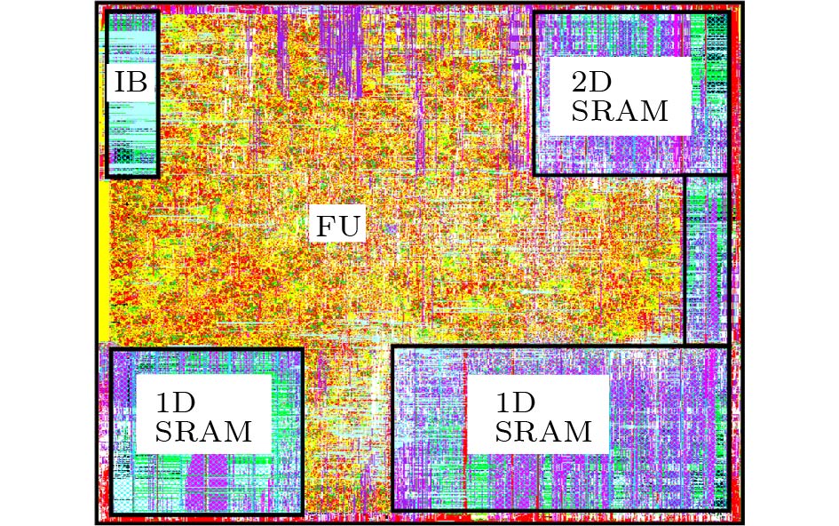
Table 3. Hardware Parameters for the AcceleratorParameter Value Note P_{x} 16 MPEs in a row of MPU P_{y} 16 MPEs in a column of MPU P_{z} 16 VPEs in VPU I_{w} 256 Instruction bit-width D_{w} 16 Data bit-width R_{n} 64 Number of control registers Inst. SRAM 32 KB Storage of instruction SRAM 2D SRAM 224 KB Storage of 2D SRAM 1D SRAM 512 KB Storage of 1D SRAM Note: Inst. is the abbreviation of instruction. Fig.19 shows the layout of the implemented accelerator, and we report the layout characteristics in Table 4. The total area of the accelerator is moderate at the cost of 7.41 mm2 at 45 nm, 1.94x and 21.6x smaller than that of the quad ARM CPU ( 4\times 3.6 mm2 at 20 nm[50]) and the x86 CPU (160 mm2 at 22 nm[51]), respectively. For fairness, we carefully scale our accelerator to corresponding technology nodes, i.e., 1.58 mm2 at 20 nm[52] and 1.63 mm2 at 22 nm[53], achieving 9.11x and 98.2x smaller area than that of quad ARM CPU and x86 CPU, respectively. The storage system (SRAM) has almost the same area cost as the computation logic (FU) (i.e., 2.98 mm2 vs 3.82 mm2), in order to accommodate at least one chunk of 1 080 p frame (e.g., ORB Desk1 and ORB EbleBox1) as well as more globally used 1D data. Thus the computation units can always process inputs without stalling.
Table 4. Accelerator Hardware Characteristics (45 nm)Hardware Module Area (mm2) Power (mW) Whole accelerator 7.41 1346.69 FU in total 4.20 1072.02 FU in MPU 3.48 964.12 FU in VPU 0.10 16.69 FU in SPU 0.02 3.64 Controller 0.23 83.00 SRAM in total 2.98 191.67 2D SRAM 0.69 64.13 1D SRAM 1.58 114.91 Inst. SRAM 0.78 12.64 8.3 Experimental Results
8.3.1 Performance
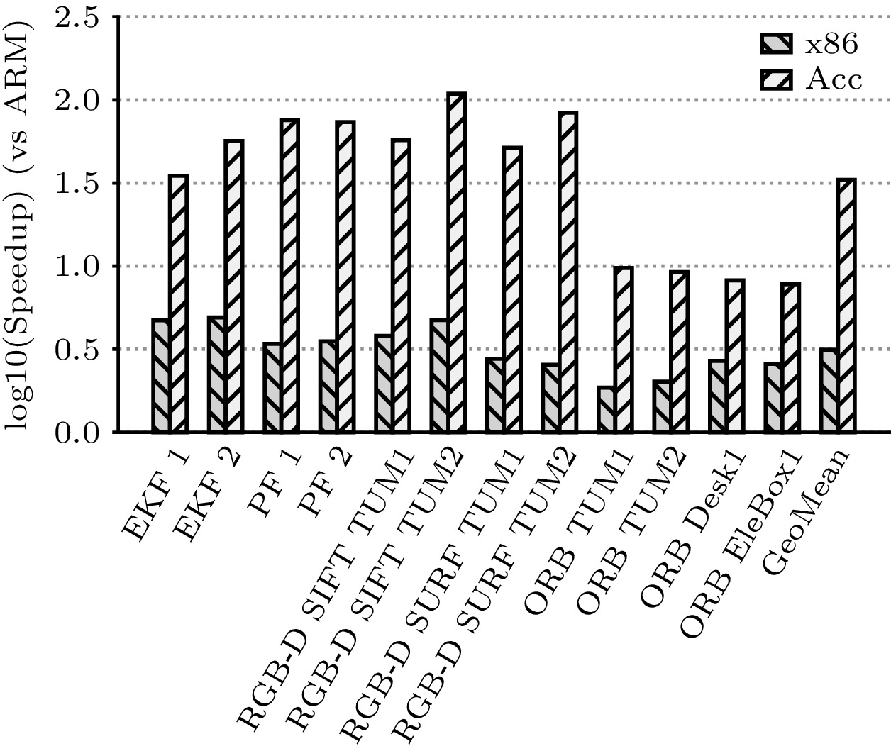
In Fig.20, we report the performance comparison of ARM, x86, and our accelerator on all 12 test cases in BenchSLAM. On average, our accelerator is 33.03x faster than the ARM CPU, while the x86 processor only achieves a 3.14x speedup over the ARM CPU. Notably, we observe that unlike the x86 CPU, which achieves almost equal acceleration on all benchmarks (1.86x–4.91x), the speedups of our accelerator over the ARM processor vary significantly on different algorithms. More specifically, our accelerator outperforms the ARM CPU 75.35x on average (51.46x–108.83x) on RGB-D SLAM algorithms, 60.13x (34.92x–75.57x) on the filter-based SLAM (i.e., EKF and PF), and only 8.73x (7.77x–9.74x) on the ORB SLAM. The main reason for the high speedup is that the relatively large proportion of operations can be mapped to the MPU (rather than the VPU) as it contains 16x more PEs than the VPU. To further validate this, we analyze the proportion of operations on the processing units and observe that 99.93% of the operations are processed on the MPU but only 0.04% on the VPU for RGB-D SLAM on average. The case is 97.53% on the MPU and 2.38% on the VPU for filter-based SLAM algorithms. For ORB SLAM, it is 92.08% on the MPU and 7.9% on the VPU. When compared with the traditional x86 CPU, the implemented accelerator achieves a 10.52 x speedup on average over all 12 benchmarks. Similarly, our accelerator also exhibits significantly different behaviors on different algorithms over x86 CPU (i.e., 15.48x, 22.37x, and 3.97x speedup on the filter-based SLAM, RGB-D SLAM, and ORB SLAM, respectively).
8.3.2 Energy Consumption
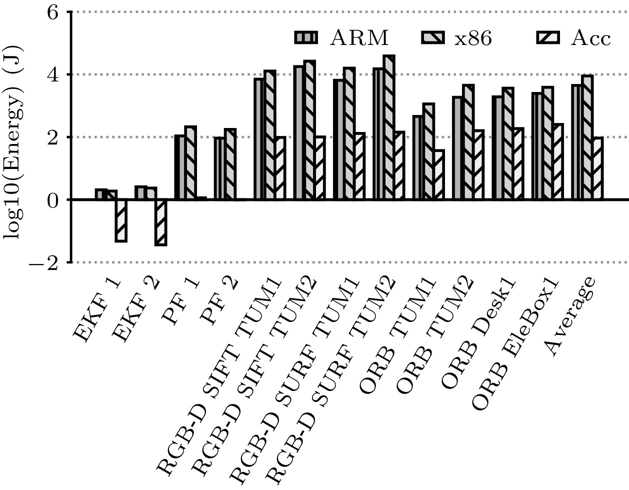
In Fig.21, we report the energy costs of the CPUs and our accelerator on all 12 test cases in BenchSLAM, where the energy costs of the DRAM accesses are also included. On average, the implemented accelerator achieves 62.64x and 112.62x better energy savings than the ARM and x86 CPUs, respectively. Moreover, when executing benchmarks with relatively small data sizes, such as the EKF and PF SLAM, our accelerator is much more energy-efficient, i.e., 75.69x and 117.08x less energy costs than the ARM and x86 CPUs, respectively, as most data can be stored in on-chip SRAMs, which thus reduces the energy costs of the DRAM accesses. Regarding vision SLAM tasks (i.e., RGB-D and ORB SLAM), our accelerator also performs well with regular computation patterns (i.e., 101.25x and 197.42x less than the ARM and x86 CPUs on the RGB-D SLAM, respectively, 10.99x and 23.37x less than the ARM and x86 CPUs on the ORB SLAM, respectively). This performance should be mainly attributed to the efficient macro instructions.
With the current configuration of parameters, our accelerator is able to process BenchSLAM in real time efficiently. Specifically, it performs all the graph-based SLAM algorithms in BenchSLAM with average frames per second (FPS) of 28.05 and the power of 467.75 mW.
9. Related Work
9.1 SLAM Algorithms
Unlike traditional SLAM algorithms that process limited data from sensors such as laser, sonar, and radar, the recent advanced vision SLAM problem raises the processing challenge with a high input data rate and a real-time requirement under a limited power budget for less powerful computation capability on mobile platforms. Typical vision SLAM algorithms such as RGB-D camera-based SLAM[17, 18] and ORB SLAM[32] require complex processing flows in both data and control. Meanwhile, emerging SLAM algorithms are evolving quickly towards wider scenarios (e.g., underwater[54], semi-dense mapping[55]) with more techniques integration (e.g., reinforcement learning[56] and spatial modeling[57]) and thus are growing in variation and complexity. Hence, our design is substantially effective in fulfilling such requirements with its high flexibility and efficiency.
9.2 Hardware Acceleration of SLAM
The SLAM problem has been evolving for many years, especially in recent years together with the advance of robotic and sensor technology. However, few researchers have worked on general hardware accelerators for SLAM algorithms.
With regard to the general-purpose processor design, research on one of the most typical solutions is conducted by Hashimoto et al.[58]. In this work, the ROS (robot operating system)[59] based SLAM is deployed on desktop operation systems such as Ubuntu on the CPU. Zhang et al.[60] presented the PerceptIn robotics vision system (PIRVS), a visual-inertial computing hardware for SLAM algorithms. The PIRVS is equipped with a multi-core processor, a global-shutter stereo camera, and an IMU (inertial measurement unit) with precise hardware synchronization.
With regard to the ASIC design, several FPGA-based architectures have been proposed. Most work focuses on only one specific SLAM algorithm. One more recent work is by Wu et al.[10]. They realized an FPGA-based customized accelerator for the DS-SLAM (semantic SLAM towards dynamic environment) algorithm. Compared with Intel i7-8750H CPU on the TUM dataset, their accelerator achieves up to 13x frame rate improvement, and up to 18x energy efficiency improvement. Liu et al.[61] proposed a heterogenous ORB-based visual SLAM system, eSLAM, which is based on an FPGA platform and dedicated to accelerating feature extraction and matching stages. When evaluating on the TUM dataset, eSLAM achieves 1.7x–3.0x speedup in the frame rate and 41x–71x improvement in the energy efficiency than those of Intel i7-4700mq CPU, while it achieves 17.8x–31x speedup and 14x–25x energy efficiency than those of the ARM Cortex-A9 processor. Boikos and Bouganis[62] also proposed an FPGA-based architecture to accelerate the large-scale direct monocular SLAM (LSD-SLAM) algorithm, achieving the real-time processing requirement. Gu et al.[63] presented an FPGA-based solution for the visual odometry based SLAM (VO-SLAM) algorithm, achieving 10x energy saving per frame than Intel i7-3770K CPU. The comparison of performance and energy consumption among the above hardware and ours is shown in Table 5. Only our accelerator supports general SLAM algorithms and achieves the best energy efficiency with an acceptable frame rate.
Table 5. Comparison with Other HardwareThere is some other work which only focuses on feature extraction stages in the SLAM algorithm. Lee and Byun[64] proposed an FPGA-based implementation to accelerate only the ORB algorithm within 18 ms, without evaluating the whole ORB-SLAM algorithm. Na and Jeong[65] proposed an FPGA solution specifically for the SURF algorithm. Jiang et al.[66] proposed a real-time SIFT hardware implementation on FPGA with task-level parallelism. Zhong et al.[67] also proposed a SIFT hardware implementation but with an FPGA+DSP architecture. Huang et al.[68] proposed an ASIC implementation of the SIFT algorithm for the real-time VGA (video graphics array) feature extraction. As a result, although many hardware implementations on FPGA/DSP for SLAM (or a part of SLAM algorithms) exist, they are specialized for specific algorithms with unchangeable IP blocks/functions and thus lack the flexibility to address other possible algorithms with high performance and efficiency. Our proposed accelerator not only supports general SLAM algorithms but also meets the performance and power requirements in the mobile systems.
10. Conclusions
In this paper, we proposed a novel hardware accelerator, equipped with a hierarchical instruction set, to efficiently cope with a broad range of SLAM algorithms at an area cost of 7.41 mm2 and a power of 1 346.67 mW. The experimental results based on our proposed BenchSLAM showed that our accelerator achieves significant performance and energy gains over the embedded platform, i.e., 33.03x speedup and 62.64x energy saving, on average. With its high performance, low energy consumption, and small area, our accelerator is suitable for integration in today's mobile robotic systems. This would significantly boost the development of the emerging mobile robot industry.
-
Figure 2. Overall flow of RGB-D SLAM[18].
Figure 3. Overall flow of ORB SLAM[32].
Figure 15. MVmV: the vector-vector multiplication on MPU. (a) Multiplication of P_{x} \times P_{y} pairs of inputs. (b) Accumulated partial productions in each MPE ( P_{x} \times P_{y} MPEs in total). (c) Propagating accumulation-summation from right to left in each MPE row. (d) Propagating accumulation-summation (Acc-Sum) from bottom to top in the left-most MPE column and outputting the final result from the top-left-most MPE.
Table 1 Subset of Proposed Instruction Set
Instruction Type Opcode Note Data LD/ST SRAM \leftrightarrow DRAM MOV SRAM \leftrightarrow SRAM RD/WR SRAM \leftrightarrow buffers Control CB Condition branch JUMP Direct/indirect jump Macro CONV Convolution operation POOL Pooling operation IMGACC Image accumulation operation BOX Image box filtering operation LOCAL EXTREMA Local extrema operation COUNTCMP Compare with counter operation Matrix MMmM/ MMaM on-MPU-matrix-mult/
add-matrix operationMMmV on-MPU-matrix-mult-vector operation MMmS/ MMaS on-MPU-matrix-mult/
add-scalar operationMVmV/ MVoV on-MPU-vector-mult/outer product-vector operation Vector VVmV/ VVaV on-VPU-vector-mult/
add-vector operationScalar SQRT on-SPU-scalar-square-root operation RANDOM on-SPU-random-generate-scalar operation Table 2 Benchmarks Configuration
Benchmark Algorithm Feature Descriptor Dataset EFK 1 EKF SLAM - Sparse map[47] EKF 2 EKF SLAM - Dense map[47] PF 1 PF SLAM - Sparse map[47] PF 2 PF SLAM - Dense map[47] RGB-D SIFT TUM1 RGB-D SLAM SIFT TUM freiburg1 scene[48] RGB-D SIFT TUM2 RGB-D SLAM SIFT TUM freiburg2 scene[48] RGB-D SURF TUM1 RGB-D SLAM SURF TUM freiburg1 scene[48] RGB-D SURF TUM2 RGB-D SLAM SURF TUM freiburg2 scene[48] ORB TUM1 ORB SLAM ORB TUM freiburg1 scene[48] ORB TUM2 ORB SLAM ORB TUM freiburg2 scene[48] ORB DESK1 ORB SLAM ORB CoRBS desk scene[49] ORB EleBox1 ORB SLAM ORB CoRBS electrical cabinet scene[49] Table 3 Hardware Parameters for the Accelerator
Parameter Value Note P_{x} 16 MPEs in a row of MPU P_{y} 16 MPEs in a column of MPU P_{z} 16 VPEs in VPU I_{w} 256 Instruction bit-width D_{w} 16 Data bit-width R_{n} 64 Number of control registers Inst. SRAM 32 KB Storage of instruction SRAM 2D SRAM 224 KB Storage of 2D SRAM 1D SRAM 512 KB Storage of 1D SRAM Note: Inst. is the abbreviation of instruction. Table 4 Accelerator Hardware Characteristics (45 nm)
Hardware Module Area (mm2) Power (mW) Whole accelerator 7.41 1346.69 FU in total 4.20 1072.02 FU in MPU 3.48 964.12 FU in VPU 0.10 16.69 FU in SPU 0.02 3.64 Controller 0.23 83.00 SRAM in total 2.98 191.67 2D SRAM 0.69 64.13 1D SRAM 1.58 114.91 Inst. SRAM 0.78 12.64 Table 5 Comparison with Other Hardware
-
[1] Durrant-Whyte H, Bailey T. Simultaneous localization and mapping: Part I. IEEE Robotics & Automation Magazine, 2006, 13(2): 99–110. DOI: 10.1109/MRA.2006.1638 022.
[2] Doucet A, De Freitas N, Gordon N. An introduction to sequential Monte Carlo methods. In Sequential Monte Carlo Methods in Practice, Doucet A, De Freitas N, Gordon N (eds.), Springer, 2001, pp.3–14. DOI: 10.1007/978-1-4757-3437-9_1.
[3] Montemerlo M, Thrun S, Roller D, Wegbreit B. FastSLAM 2.0: An improved particle filtering algorithm for simultaneous localization and mapping that provably converges. In Proc. the 18th International Joint Conference on Artificial Intelligence (IJCAI), Aug. 2003, pp.1151–1156.
[4] Guivant J E, Nebot E M. Optimization of the simultaneous localization and map-building algorithm for real-time implementation. IEEE Trans. Robotics and Automation, 2001, 17(3): 242–257. DOI: 10.1109/70.938382.
[5] Olson E B. Real-time correlative scan matching. In Proc. the 2009 IEEE International Conference on Robotics and Automation, May 2009, pp.4387–4393. DOI: 10.1109/ROBOT.2009.5152375.
[6] Yan B, Xin J, Shan M, Wang Y Q. CUDA implementation of a parallel particle filter for mobile robot pose estimation. In Proc. the 14th IEEE Conference on Industrial Electronics and Applications (ICIEA), Jun. 2019, pp.578–582. DOI: 10.1109/ICIEA.2019.8833856.
[7] Mittal R, Pathak V, Mithal A. A novel approach to optimize SLAM using GP-GPU. In Proc. International Conference on Data Science and Applications, Ray K, Roy K C, Toshniwal S K, Sharma H, Bandyopadhyay A (eds.), Springer, 2021, pp.273–280. DOI: 10.1007/978-981-15-7561-7_22.
[8] Nardi L, Bodin B, Zia M Z, Mawer J, Nisbet A, Kelly P H J, Davison A J, Lujan M, O'Boyle M F P, Riley G, Topham N, Furber S. Introducing SLAMBench, a performance and accuracy benchmarking methodology for SLAM. In Proc. the 2015 IEEE International Conference on Robotics and Automation (ICRA), May 2015, pp.5783–5790. DOI: 10.1109/ICRA.2015.7140009.
[9] Peng T, Zhang D N, Liu R X, Asari V K, Loomis J S. Evaluating the power efficiency of visual SLAM on embedded GPU systems. In Proc. the 2019 IEEE National Aerospace and Electronics Conference (NAECON), July 2019, pp.117–121. DOI: 10.1109/NAECON46414.2019.9058059.
[10] Wu Y K, Luo L, Yin S J, Yu M Q, Qiao F, Huang H Z, Shi X S, Wei Q, Liu X J. An FPGA based energy efficient DS-SLAM accelerator for mobile robots in dynamic environment. Applied Sciences, 2021, 11(4): 1–15. DOI: 10.3390/app11041828.
[11] Bouhoun S, Sadoun R, Adnane M. OpenCL implementation of a SLAM system on an SoC-FPGA. Journal of Systems Architecture, 2020, 111: 101825. DOI: 10.1016/j.sysarc.2020.101825.
[12] Nguyen D D, El Ouardi A, Rodríguez S, Bouaziz S. FPGA implementation of HOOFR bucketing extractor-based real-time embedded SLAM applications. Journal of Real-Time Image Processing, 2021, 18(3): 525–538. DOI: 10.1007/s11554-020-00986-9.
[13] Czarnowski J, Laidlow T, Clark R, Davison A J. DeepFactors: Real-time probabilistic dense monocular SLAM. IEEE Robotics and Automation Letters, 2020, 5(2): 721–728. DOI: 10.1109/LRA.2020.2965415.
[14] Li Y Y, Brasch N, Wang Y D, Navab N, Tombari F. Structure-SLAM: Low-drift monocular SLAM in indoor environments. IEEE Robotics and Automation Letters, 2020, 5(4): 6583–6590. DOI: 10.1109/LRA.2020.3015456.
[15] Gomez-Ojeda R, Moreno F A, Zuniga-Noël D, Scaramuzza D, Gonzalez-Jimenez J. PL-SLAM: A stereo SLAM system through the combination of points and line segments. IEEE Trans. Robotics, 2019, 35(3): 734–746. DOI: 10.1109/TRO.2019.2899783.
[16] Li X, Li Y Y, Örnek E P, Lin J L, Tombari F. Co-Planar parametrization for Stereo-SLAM and visual-inertial odometry. IEEE Robotics and Automation Letters, 2020, 5(4): 6972–6979. DOI: 10.1109/LRA.2020.3027230.
[17] Kolhatkar C, Wagle K. Review of SLAM algorithms for indoor mobile robot with LIDAR and RGB-D camera technology. In Innovations in Electrical and Electronic Engineering: Proceedings of ICEEE 2020, Favorskaya M N, Mekhilef S, Pandey R K, Singh N (eds.), Springer, 2021, pp.397–409. DOI: 10.1007/978-981-15-4692-1_30.
[18] Endres F, Hess J, Sturm J, Cremers D, Burgard W. 3-D mapping with an RGB-D camera. IEEE Trans. Robotics, 2014, 30(1): 177–187. DOI: 10.1109/TRO.2013.2279412.
[19] Kala S, Jose B R, Mathew J, Nalesh S. High-performance CNN accelerator on FPGA using unified winograd-GEMM architecture. IEEE Trans. Very Large Scale Integration (VLSI) Systems, 2019, 27(12): 2816–2828. DOI: 10.1109/TVLSI.2019.2941250.
[20] Tavakoli M R, Sayedi S M, Khaleghi M J. A high throughput hardware CNN accelerator using a novel multi-layer convolution processor. In Proc. the 28th Iranian Conference on Electrical Engineering (ICEE), Aug. 2020. DOI: 10.1109/ICEE50131.2020.9260785.
[21] Lowe D G. Distinctive image features from scale-invariant keypoints. International Journal of Computer Vision, 2004, 60(2): 91–110. DOI: 10.1023/B:VISI.0000029664.9961 5.94.
[22] Knyazev A V. A preconditioned conjugate gradient method for eigenvalue problems and its implementation in a subspace. In Numerical Treatment of Eigenvalue Problems Vol. 5/Numerische Behandlung von Eigenwertaufgaben Band 5, Albrecht J, Collatz L, Hagedorn P, Velte W (eds.), Birkhäuser, 1991, pp.143–154. DOI: 10.1007/978-3-0348-6332-2_11.
[23] Strasdat H, Montiel J M M, Davison A J. Visual SLAM: Why filter? Image and Vision Computing, 2012, 30(2): 65–77. DOI: 10.1016/j.imavis.2012.02.009.
[24] Tan F, Lohmiller W, Slotine J J. Analytical SLAM without linearization. arXiv: 1512.08829, 2016. https://arxiv.org/abs/1512.08829, Oct. 2023.
[25] Arulampalam M S, Maskell S, Gordon N, Clapp T. A tutorial on particle filters for online nonlinear/non-Gaussian Bayesian tracking. IEEE Trans. Signal Processing, 2002, 50(2): 174–188. DOI: 10.1109/78.978374.
[26] Grisetti G, Stachniss C, Burgard W. Improved techniques for grid mapping with rao-blackwellized particle filters. IEEE Trans. Robotics, 2007, 23(1): 34–46. DOI: 10.1109/TRO.2006.889486.
[27] Bailey T, Durrant-Whyte H. Simultaneous localization and mapping (SLAM): Part II. IEEE Robotics & Automation Magazine, 2006, 13(3): 108–117. DOI: 10.1109/MRA.2006.1678144.
[28] Lu F, Milios E. Globally consistent range scan alignment for environment mapping. Autonomous Robots, 1997, 4(4): 333–349. DOI: 10.1023/A:1008854305733.
[29] Grisetti G, Kummerle R, Stachniss C, Burgard W. A tutorial on graph-based SLAM. IEEE Intelligent Transportation Systems Magazine, 2010, 2(4): 31–43. DOI: 10.1109/MITS.2010.939925.
[30] Rosten E, Drummond T. Machine learning for high-speed corner detection. In Proc. the 9th European Conference on Computer Vision (ECCV), May 2006, pp.430–443. DOI: 10.1007/11744023_34.
[31] Calonder M, Lepetit V, Strecha C, Fua P. BRIEF: Binary robust independent elementary features. In Proc. the 11th European Conference on Computer Vision (ECCV), Sept. 2010, pp.778–792. DOI: 10.1007/978-3-642-15561-1_56.
[32] Mur-Artal R, Montiel J M M, Tardós J D. ORB-SLAM: A versatile and accurate monocular SLAM system. IEEE Trans. Robotics, 2015, 31(5): 1147–1163. DOI: 10.1109/TRO.2015.2463671.
[33] Bay H, Tuytelaars T, Van Gool L. SURF: Speeded up robust features. In Proc. the 9th European Conference on Computer Vision, May 2006, pp.404–417. DOI: 10.1007/11744023_32.
[34] Fischler M A, Bolles R C. Random sample consensus: A paradigm for model fitting with applications to image analysis and automated cartography. Communications of the ACM, 1981, 24(6): 381–395. DOI: 10.1145/358669.358692.
[35] Besl P J, McKay N D. A method for registration of 3-D shapes. In Proc. the SPIE 1611, Sensor Fusion IV: Control Paradigms and Data Structures, Apr. 1992, pp.586–606. DOI: 10.1117/12.57955.
[36] Censi A. An ICP variant using a point-to-line metric. In Proc. the 2008 IEEE International Conference on Robotics and Automation, May 2008, pp.19–25. DOI: 10.1109/ROBOT.2008.4543181.
[37] Rusinkiewicz S, Levoy M. Efficient variants of the ICP algorithm. In Proc. the 3rd International Conference on 3-D Digital Imaging and Modeling, May 28–Jun. 1, 2001, pp.145–152. DOI: 10.1109/IM.2001.924423.
[38] Kümmerle R, Grisetti G, Strasdat H, Konolige K, Burgard W. g2o: A general framework for graph optimization. In Proc. the 2011 IEEE International Conference on Robotics and Automation (ICRA), May 2011, pp.3607–3613. DOI: 10.1109/ICRA.2011.5979949.
[39] Linsen L. Point cloud representation. Technical Report, Faculty of Computer Science, University of Karlsruhe: Univ., Fak. für Informatik, Bibliothek, 2001. https://geom.ivd.kit.edu/downloads/pubs/publinsen_2001.pdf, July 2020.
[40] Campos C, Elvira R, Rodríguez J J G, Montiel J M M, Tardós J D. ORB-SLAM3: An accurate open-source library for visual, visual-inertial, and multimap SLAM. IEEE Trans. Robotics, 2021, 37(6): 1874–1890. DOI: 10.1109/TRO.2021.3075644.
[41] Mucci P J, Browne S, Deane C, Ho G. PAPI: A portable interface to hardware performance counters. https://icl.utk.edu/projectsfiles/papi/pubs/dodugc99-papi.pdf, Nov. 2023.
[42] Luk C K, Cohn R, Muth R, Patil H, Klauser A, Lowney G, Wallace S, Reddi V J, Hazelwood K. Pin: Building customized program analysis tools with dynamic instrumentation. In Proc. the 2005 ACM SIGPLAN Conference on Programming Language Design and Implementation (PLDI), Jun. 2005, pp.190–200. DOI: 10.1145/1065010.1065034.
[43] Eyerman S, Eeckhout L, Karkhanis T, Smith J E. A performance counter architecture for computing accurate CPI components. In Proc. the 12th International Conference on Architectural Support for Programming Languages and Operating Systems, Oct. 2006, pp.175–184. DOI: 10.1145/1168857.1168880.
[44] Bird S, Phansalkar A, John L K, Mericas A, Indukuru R. Performance characterization of SPEC CPU benchmarks on Intel's Core microarchitecture based processor. In Proc. SPEC Benchmark Workshop, Jan. 2007.
[45] Jeong Y, Nister D, Steedly D, Szeliski R, Kweon I S. Pushing the envelope of modern methods for bundle adjustment. In Proc. the 2010 IEEE Computer Society Conference on Computer Vision and Pattern Recognition (CVPR), Jun. 2010, pp.1474–1481. DOI: 10.1109/CVPR.2010.5539795.
[46] Guennebaud G, Jacob B. Eigen v3. Technical Report, CGLibs, 2010. https://eigen.tuxfamily.org, October 2023.
[47] Bailey T, Nieto J, Nebot E. Consistency of the FastSLAM algorithm. In Proc. the 2006 IEEE International Conference on Robotics and Automation (ICRA), May 2006, pp.424–429. DOI: 10.1109/ROBOT.2006.1641748.
[48] Sturm J, Engelhard N, Endres F, Burgard W, Cremers D. A benchmark for the evaluation of RGB-D SLAM systems. In Proc. the 2012 IEEE/RSJ International Conference on Intelligent Robots and Systems (IROS), Oct. 2012, pp.573–580. DOI: 10.1109/IROS.2012.6385773.
[49] Wasenmüller O, Meyer M, Stricker D. CoRBS: Comprehensive RGB-D benchmark for SLAM using Kinect v2. In Proc. the 2016 IEEE Winter Conference on Applications of Computer Vision (WACV), Mar. 2016. DOI: 10.1109/WACV.2016.7477636.
[50] Joseph J. Huawei's Kirin 930 balances power & performance using Cortex A53e cores! 2015. https://www.gizmochina.com/2015/03/27/huawei-reveals-kirin-930-uses-enhanced-cortex-a53e-cores/, October 2023.
[51] Shimpi A L, Smith R. The Intel Ivy Bridge (Core i7 3770k) review. Technical Report, Intel Research, 2012. https://www.anandtech.com/show/5771/theintel-ivybridge-core-i7-3770k-review/3, October 2023.
[52] Stillmaker A, Baas B. Scaling equations for the accurate prediction of CMOS device performance from 180 nm to 7 nm. Integration, 2017, 58: 74–81. DOI: 10.1016/j.vlsi.2017.02.002.
[53] Sarangi S, Baas B. DeepScaleTool: A tool for the accurate estimation of technology scaling in the deep-submicron era. In Proc. the 2021 IEEE International Symposium on Circuits and Systems (ISCAS), May 2021. DOI: 10.1109/ISCAS51556.2021.9401196.
[54] Hong S, Kim J. Three-dimensional visual mapping of underwater ship hull surface using piecewise-planar SLAM. International Journal of Control, Automation and Systems, 2020, 18(3): 564–574. DOI: 10.1007/s12555-019-0646-8.
[55] Wu L Y, Wan W G, Yu X Q, Ye C K, Muzahid A A M. A novel augmented reality framework based on monocular semi-dense simultaneous localization and mapping. Computer Animation and Virtual Worlds, 2020, 31(3): e1922. DOI: 10.1002/cav.1922.
[56] Wen S H, Zhao Y F, Yuan X, Wang Z T, Zhang D, Manfredi L. Path planning for active SLAM based on deep reinforcement learning under unknown environments. Intelligent Service Robotics, 2020, 13(2): 263–272. DOI: 10.1007/s11370-019-00310-w.
[57] Yang J J, Wang C, Zhang Q, Chang B S, Wang F, Wang X L, Wu M. Modeling of laneway environment and locating method of roadheader based on self-coupling and hector SLAM. In Proc. the 5th International Conference on Electromechanical Control Technology and Transportation (ICECTT), May 2020, pp.263–268. DOI: 10.1109/ICECTT50890.2020.00067.
[58] Hashimoto K, Saito F, Yamamoto T, Ikeda K. A field study of the human support robot in the home environment. In Proc. the 2013 IEEE Workshop on Advanced Robotics and Its Social Impacts, Nov. 2013, pp.143–150. DOI: 10.1109/ARSO.2013.6705520.
[59] Quigley M, Conley K, Gerkey B, Faust J, Foote T, Leibs J, Wheeler R, Ng A. ROS: An open-source robot operating system. In Proc. the 2009 ICRA Workshop on Open Source Software, May 2009.
[60] Zhang Z, Liu S S, Tsai G, Hu H B, Chu C C, Zheng F. PIRVS: An advanced visual-inertial SLAM system with flexible sensor fusion and hardware co-design. In Proc. the 2018 IEEE International Conference on Robotics and Automation (ICRA), May 2018, pp.3826–3832. DOI: 10.1109/ICRA.2018.8460672.
[61] Liu R Z, Yang J L, Chen Y R, Zhao W S. eSLAM: An energy-efficient accelerator for real-time ORB-SLAM on FPGA platform. In Proc. the 56th Annual Design Automation Conference, Jun. 2019, Article No. 193. DOI: 10.1145/3316781.3317820.
[62] Boikos K, Bouganis C S. A scalable FPGA-based architecture for depth estimation in SLAM. In Proc. the 15th International Symposium on Applied Reconfigurable Computing (ARC), Apr. 2019, pp.181–196. DOI: 10.1007/978-3-030-17227-5_14.
[63] Gu M Y, Guo K Y, Wang W Q, Wang Y, Yang H Z. An FPGA-based real-time simultaneous localization and mapping system. In Proc. the 2015 International Conference on Field Programmable Technology (FPT), Dec. 2015, pp.200–203. DOI: 10.1109/FPT.2015.7393150.
[64] Lee K Y, Byun K J. A hardware design of optimized ORB algorithm with reduced hardware cost. Advanced Science and Technology Letters, 2013, 43(3): 58–62. DOI: 10.14257/ASTL.2013.43.11.
[65] Na E S, Jeong Y J. FPGA implementation of SURF-based feature extraction and descriptor generation. Journal of Korea Multimedia Society, 2013, 16(4): 483–492. DOI: 10.9717/KMMS.2013.16.4.483.
[66] Jiang J, Li X Y, Zhang G J. SIFT hardware implementation for real-time image feature extraction. IEEE Trans. Circuits and Systems for Video Technology, 2014, 24(7): 1209–1220. DOI: 10.1109/TCSVT.2014.2302535.
[67] Zhong S, Wang J H, Yan L X, Kang L, Cao Z G. A real-time embedded architecture for SIFT. Journal of Systems Architecture, 2013, 59(1): 16–29. DOI: 10.1016/j.sysarc.2012.09.002.
[68] Huang F C, Huang S Y, Ker J W, Chen Y C. High-performance SIFT hardware accelerator for real-time image feature extraction. IEEE Trans. Circuits and Systems for Video Technology, 2012, 22(3): 340–351. DOI: 10.1109/TCSVT.2011.2162760.
-
期刊类型引用(1)
1. Nagi Reddy Kandukuri, Madhushekhar Yadla, Saleha Butool, et al. Analysis of Cloud Computing Technology Network Software Educational Affairs Human Resources Development Process and its Applications. 2024 International Conference on Science Technology Engineering and Management (ICSTEM),  必应学术
必应学术
其他类型引用(0)
-
其他相关附件


 下载:
下载:

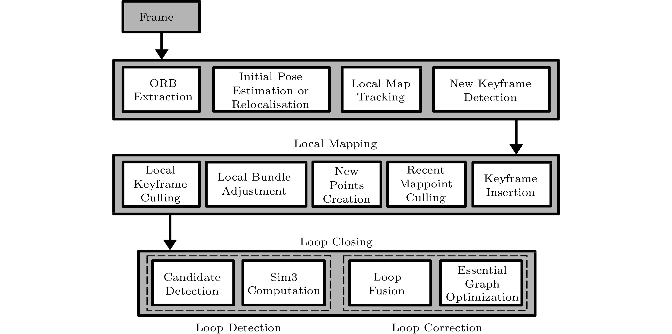
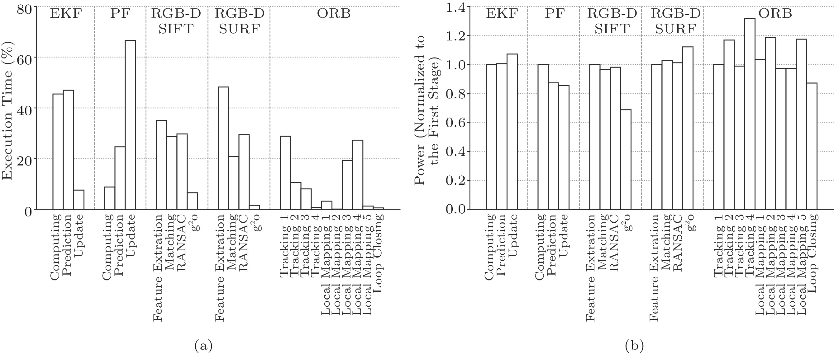
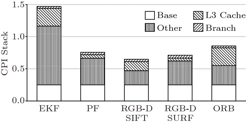
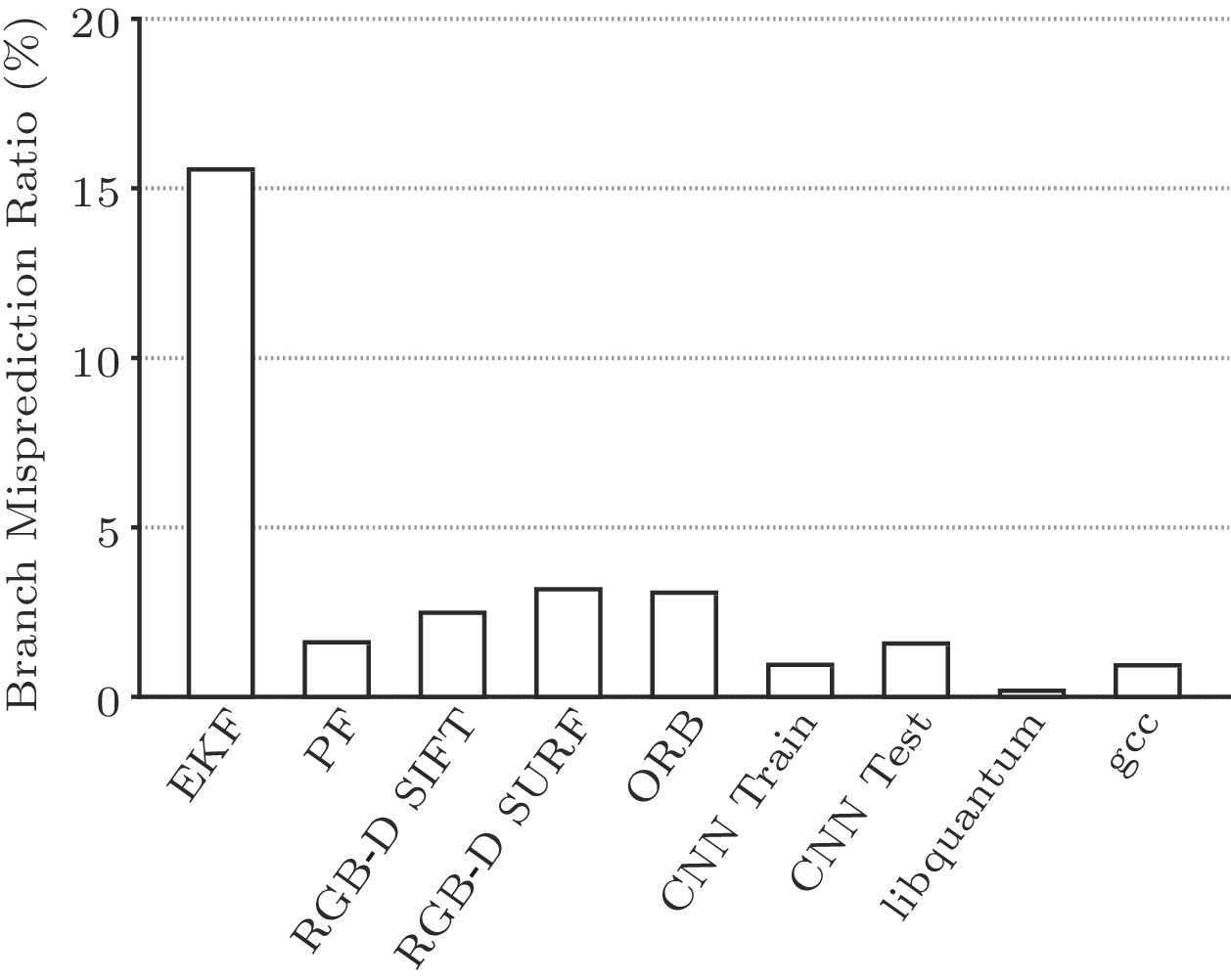
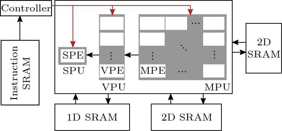
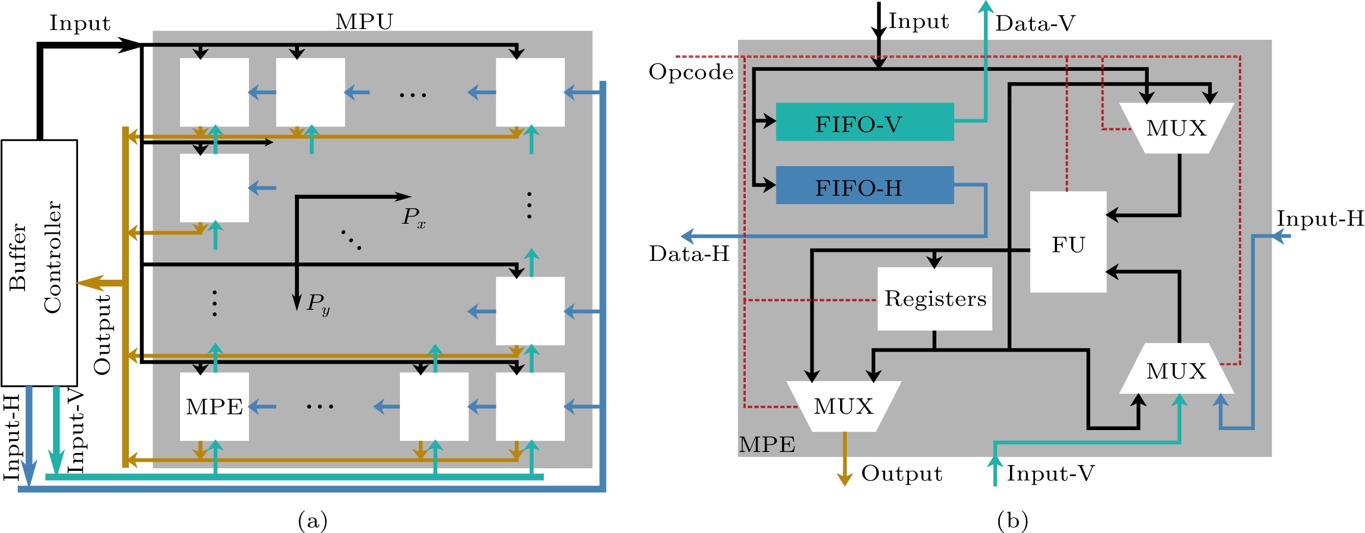
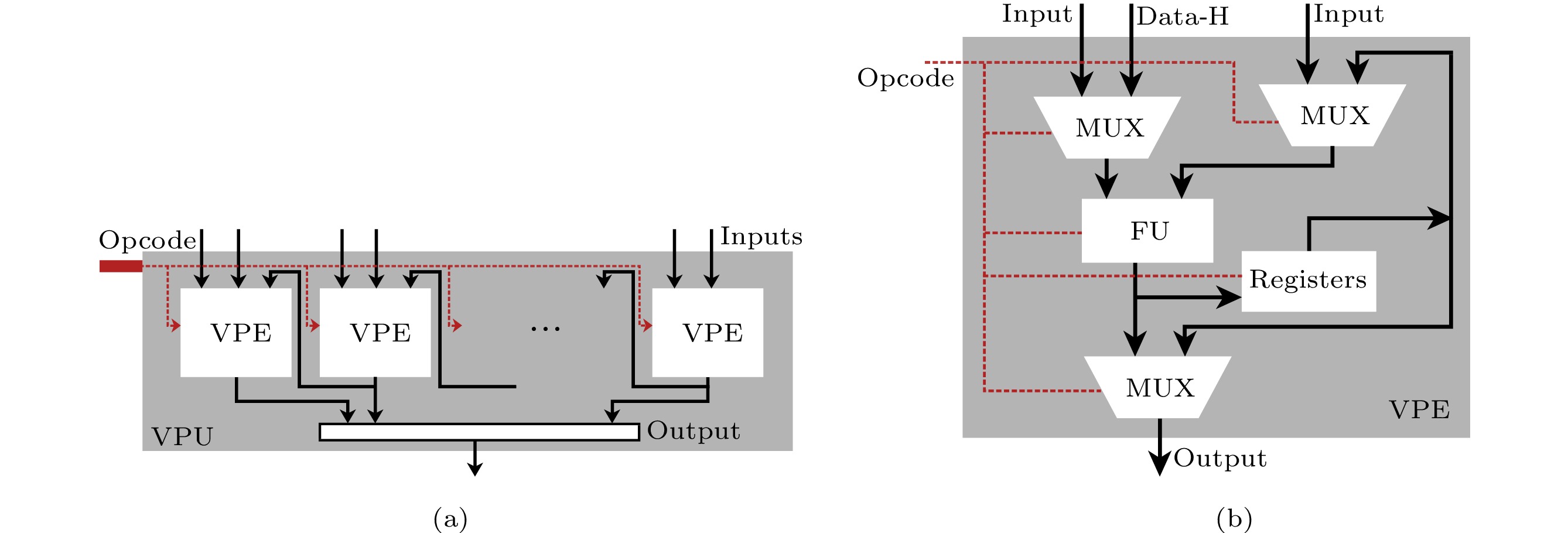

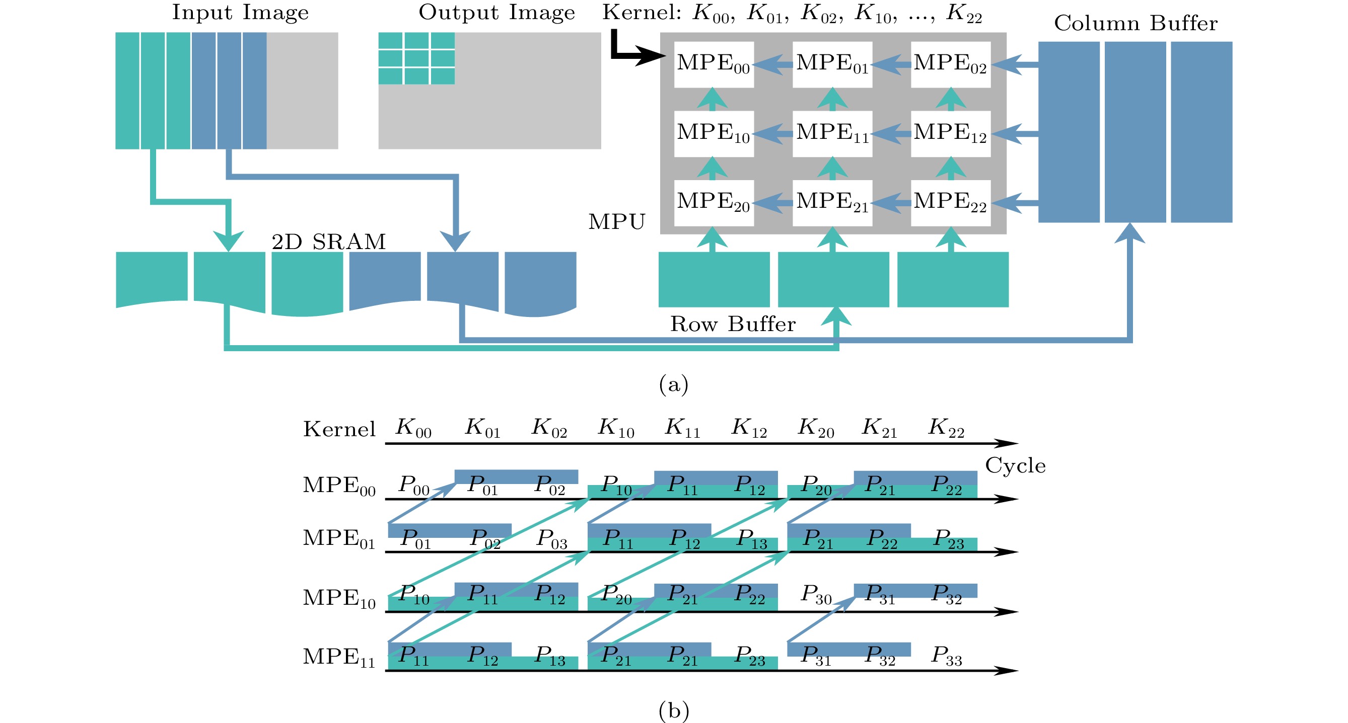
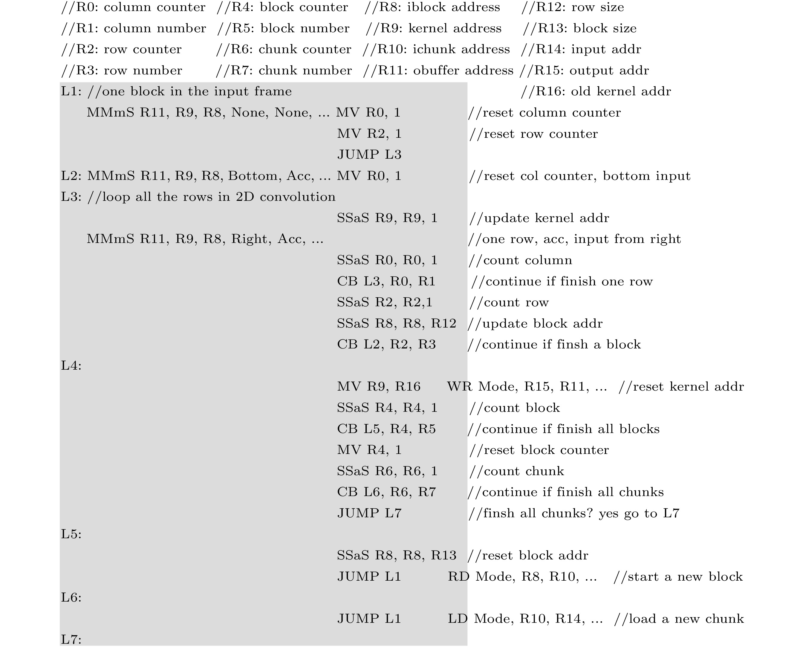
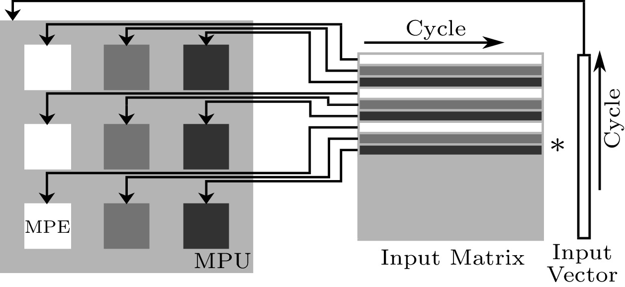
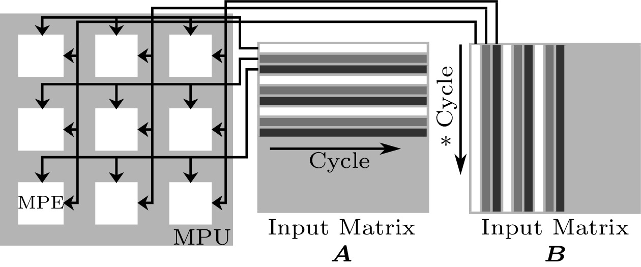


 : subtraction.

