不可靠观测下的地下恶劣环境无人机定位
-
摘要:研究背景
随着地下资源开发的不断深入和扩展,无人机在地下自动化和智能化发展中发挥着至关重要的作用。在安全监测、设备检查、应急救援等方面,由于地下环境恶劣,通过工业机器人进行智能监控可能导致数据采集失败。无人机作为一种新型地下探测工具,适合进入有污染和危险的恶劣地区作业。无人机体积小、重量轻,在完成某些特定工作方面具有显著优势,可以携带不同类型的设备,并根据业务需求执行不同的任务。此外,无人机在地下火灾监测和消防方面非常重要,也是推广地下应急无线通信网络的有效途径,使工程师能够远程获取地下工作区域的数据。准确可靠的无人机定位是地下智能化开发的基础,不仅降低了工人的劳动强度和风险,还提高了生产效率。
目的恶劣地下环境中的无人机定位主要面临以下挑战:一方面,UWB的距离测量信息不可靠,受多径效应、天线延迟、高温、高湿、高尘等多种因素影响。此外,地下空间封闭、受限以及地质结构不均匀等问题,将进一步加剧多径效应,导致出现完全错误的距离测量信息。另一方面,地下空间中的大型设备和支撑结构等障碍物引起的信号遮挡、反射、散射等,易造成UWB信号的延迟到达、丢包甚至连续丢包。测量更新是基于滤波的定位方法的关键步骤,UWB信号丢失将导致测量更新失败,进而引发定位性能的急剧下降。因此,亟需一个新的定位框架以实现恶劣地下环境中的准确、鲁棒无人机定位。本文从算法层面入手,主要研究以地下车库和地下矿山为代表的恶劣地下环境中的多传感器融合定位问题。
方法通过融合UWB与IMU,本文提出一种新颖的无人机定位框架UO-EKF。首先,利用IMU进行无人机运动补偿,并基于最小化新息误差协方差矩阵引入自适应因子,动态调整系统噪声与测量噪声,进而修正UWB距离测量误差,提高无人机定位准确性。进一步,设计基于系统状态约束的测量更新策略,将无约束的状态估计投影到约束平面上并利用拉格朗日乘数法求解,以补偿UWB距离测量的间歇性丢失。此外,基于自回归模型重构UWB距离测量,解决UWB盲区问题,从而实现恶劣地下环境中精确鲁棒的无人机定位。
结果本文通过仿真和实验对所提出定位框架的性能进行了评估。首先,在Gazebo平台比较UO-EKF中不同方法和策略的定位精度,以及不同参数下UO-EKF的性能,以验证其可行性。进一步,将所提出的UO-EKF在地下车库和煤矿井下进行现场实验并与现有前沿定位算法进行比较,以验证实际效果。结果表明UO-EKF在地下车库和煤矿井下的定位均方根误差分别为19.2cm和21.7cm。与最新相关方法相比,定位性能提高了16.9%。
结论在本文中,我们设计了一种新颖的无人机定位框架UO-EKF,以处理恶劣地下环境中的距离测量信息异常和丢包问题。基于UWB和IMU的融合,在定位框架中提出了AEKF、CEKF和AREKF三种定位算法。AEKF用于检测和校正异常值,提高了定位的准确性。此外,CEKF和AREKF用于补偿距离测量信息的丢失,进一步提高了定位性能。仿真和实验表明,所提出的UO-EKF是可行的,可以在恶劣地下环境中获得更好的鲁棒性和准确性。在今后的工作中,我们将进一步完善定位算法,拓展应用领域。
Abstract:The accurate and robust unmanned aerial vehicle (UAV) localization is significant due to the requirements of safety-critical monitoring and emergency wireless communication in hostile underground environments. Existing range-based localization approaches fundamentally rely on the assumption that the environment is relatively ideal, which enables a precise range for localization. However, radio propagation in the underground environments may be dramatically influenced by various equipments, obstacles, and ambient noises. In this case, inaccurate range measurements and intermittent ranging failures inevitably occur, which leads to severe localization performance degradation. To address the challenges, a novel UAV localization scheme is proposed in this paper, which can effectively handle unreliable observations in hostile underground environments. We first propose an adaptive extended Kalman filter (EKF) based on the fusion of ultra-wideband (UWB) and inertial measurement unit (IMU) to detect and adjust the inaccurate range measurements. Aiming to deal with intermittent ranging failures, we further design the constraint condition by limiting the system state. Specifically, the auto-regressive model is proposed to implement the localization in the ranging blind areas by reconstructing the lost measurements. Finally, extensive simulations have been conducted to verify the effectiveness. We carry out field experiments in an underground garage and a coal mine based on P440 UWB sensors. Results show that the localization accuracy is improved by 16.9% compared with the recent methods in the hostile underground environments.
-
1. Introduction
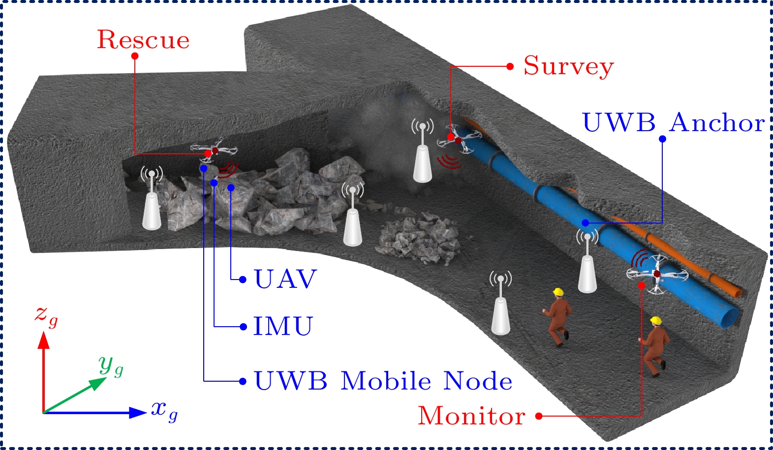
With the development of underground equipment automation, the unmanned aerial vehicle (UAV) plays a crucial role in unmanned and automated underground scenes, which is mainly utilized for safety monitoring, equipment inspection, emergency rescue, and so on. It not only reduces the labor intensity and risk of workers but also improves production efficiency[1]. Due to the complex terrain in actual underground environments, intelligent monitoring through industrial robots may lead to the failure of data acquisition[2]. UAV, as a novel detection tool in the underground environments, is suitable for entering harsh areas with pollution and danger for operation. The UAV with its small size and light weight has significant advantages to complete some specified work as shown in Fig.1, which can carry different types of equipments and perform different tasks according to operational demands[3]. In addition, UAV is very important for underground fire monitoring and fire fighting, and it is also an effective way to promote the underground emergency wireless communication network, enabling engineers to remotely capture data in underground work areas[4–6]. Accurate and reliable UAV localization is the basis of intelligent underground operations, but it remains one of the most challenging issues in hostile underground environments.
There exist many wireless localization schemes, which mainly rely on WiFi[7], Bluetooth[8], RFID[9], ZigBee[10], or LTE[11] to realize localization. Compared with the above wireless signals, the ultra-wideband (UWB) technology[12] has the advantages of low energy consumption, strong anti-multipath effect, and high accuracy. UWB can provide absolute range information, but the ranging accuracy is greatly reduced in the complex not-line-of-sight (NLOS) underground scenes. The inertial measurement unit (IMU) can provide orientation and relative displacement information. Consequently, the fusion of UWB and IMU is an ideal solution for UAV localization in hostile environments[13, 14], which can overcome the lack of orientation information, the long-term drift error, and obtain better performances[15–17].
Many excellent algorithms were proposed for sensor information fusion, such as extended Kalman filter (EKF)[18], unscented Kalman filter (UKF)[19], cubature Kalman filter[20], particle filter[21], and nonlinear optimization[22]. Among these fusion algorithms, EKF is the most commonly utilized method for nonlinear systems[23–25], in which the state propagation is realized by low-cost IMU and the measurement is updated by UWB ranging. The aforementioned typical filtering methods assume that the ranging measurements are available. However, inaccurate range measurements and intermittent ranging failures often occur in hostile underground environments. Directly adopting the classical EKF localization schemes is infeasible and may lead to serious localization performance degradation.
This paper aims to achieve accurate and robust UAV localization in hostile underground environments and correspondingly conducts experiments in typical hostile underground scenarios (an underground garage and an underground coal mine). We improve the multi-sensor fusion algorithms[15, 26, 27] to enhance the localization performance. A design is proposed to detect and correct the inaccurate UWB ranging measurements. Besides, the influence of measurement losses on localization performance is reduced by setting system constraints and reconstructing UWB range measurements. Specifically, the main contributions can be summarized as follows.
∙ To the best of our knowledge, we are the first to propose a novel UAV localization framework for dealing with unreliable observations based on the fusion of UWB and IMU, which can achieve accurate and robust UAV localization in hostile underground environments.
∙ An adaptive EKF is proposed to detect and correct outliers. We further introduce the state constraint to compensate for intermittent UWB signal losses. Moreover, an auto-regressive model is employed to reconstruct measurements in blind areas of UWB.
∙ The localization performance is evaluated through extensive simulations and field experiments in an underground garage and an underground coal mine.
The rest of the paper is organized as follows. Section 2 briefly introduces the motivation behind this work and preliminaries. The proposed UAV localization framework and algorithms in hostile underground environments are proposed and elaborated in Sections 3-5. In Section 6, the simulations and experiments are carried out, and the performance evaluation is further presented. Section 7 introduces related work, and Section 8 summarizes the paper.
2. Background
In this section, the UWB-ranging experiments in an underground garage and an underground coal mine are first presented. Then, the movement model based on the fusion of UWB and IMU is introduced.
2.1 UWB Ranging in Various Scenarios
The underground environments generally encompass underpasses, subways, basements, underground shopping malls, underground garages, underground coal mines, and so on. This paper takes the widely applied underground garages and the extremely hostile underground coal mines as the representatives of hostile underground environments.
Underground garages are widely applied in urban areas and are typical underground spaces. Compared with the common underground environments (such as subways, basements, and underground shopping malls), there are significant obstacles such as numerous vehicles, pipes, and concrete structures in the underground garages. These obstacles bring the inaccuracy of wireless signal arrival time or angles, leading to a degradation of localization performances. In China, coal is the main energy source, and most coal mines belong to underground mines with extremely hostile environments. The localization in underground coal mines faces the following challenges. The mine tunnel is narrow, closed, restricted, and the geological structure is uneven, resulting in serious multipath effects. Signal reflection caused by large production equipments and metal support structures in mines further aggravates the multipath effect. Besides, high temperature, high humidity, high dust, noises, and non-line-of-sight have an obvious influence on UWB signals in harsh coal mines. These factors may make the ranging and communication modules work abnormally or even fail[28], resulting in localization failure.
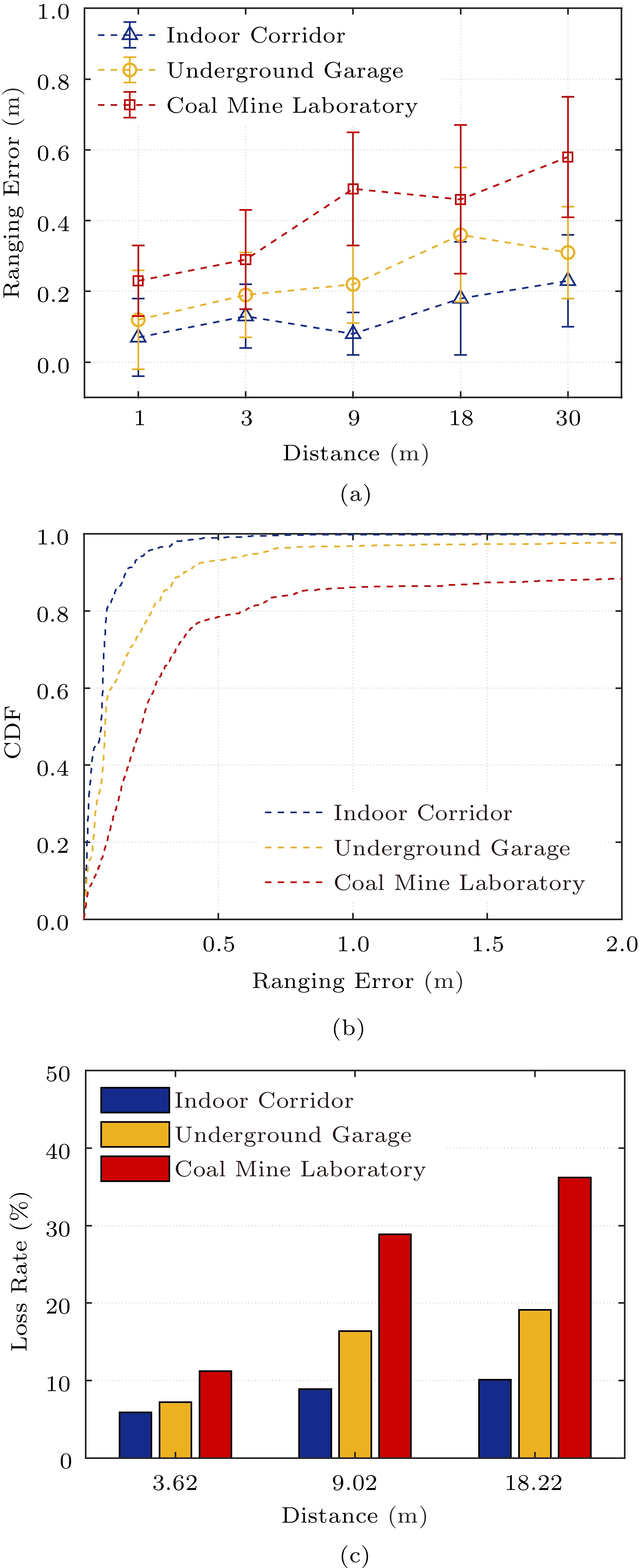
The critical step of filter-based localization methods is measurement update. The unreliable UWB signals may cause measurement updates to pause. Note that if the signal cannot reach the receiver within the sampling period[29], the delayed signal is also viewed as measurement loss. To elaborate on the issues mentioned above, we record the UWB measurements in an indoor corridor, an underground garage, and a coal mine laboratory, respectively. Compared with indoor scenarios, UWB measurements have larger ranging errors and loss rates in practical coal mines, followed by underground garages[30]. Our experimental results also verify it. Fig.2(a) shows the mean and variance of ranging errors with different ranges and scenarios. With the ranging range from 3 m to 30 m, the ranging errors increase by 61.5%, 63.2%, and 96.6%, respectively. The cumulative distribution function (CDF) of UWB ranging errors is presented in Fig.2(b). At the actual range 9.02 m, it can be seen that more than 20% of the ranging errors is greater than 0.5m, and more than 10% of the ranging errors is greater than 2 m in the coal mine laboratory. Fig.2(c) shows the measurement loss rate in three scenarios, where we conduct more than 10 000 ranging experiments. The farther the range between two nodes, the more serious the loss of measurements. Especially, the loss rates in the three scenarios are 8.9%, 16.4%, and 28.9% at 9.02 m, respectively.
From the above experiments, we argue that inaccurate ranging is a common issue, which is more pronounced in underground garages and coal mines, and may be accompanied by the loss of range measurements. All the above limitations will bring severe localization performance degradation if directly using the classical EKF. Hence, a new localization framework is required to provide accurate and robust UAV localization in hostile underground environments, which forms the motivation of our work. This paper starts from the algorithm level rather than improving the ranging accuracy through signal processing.
2.2 UAV Movement Model
We assume that the UAV follows a variable acceleration motion. Considering the instability of IMU, we let the acceleration bias {\boldsymbol{a}}_b = {({a_{bx}},\ {a_{by}},\ {a_{bz}})^{\rm{T}}} be a part of the state vector to be estimated, as well as the UAV position {\boldsymbol{p}} = {({p_x},\ {p_y},\ {p_z})^{\rm{T}}} and velocity {\boldsymbol{v}} = {({v_x}, } {\ {v_y},\ {v_z})^{\rm{T}}} . Then an augmented state vector {\boldsymbol{x}} \in {{\mathbb{R}}^9} is established according to (1). Based on the Markov theory, the current state of the UAV is only related to the last state. The UAV movement model consists of the system motion equation and the observation equation, which are defined as (2) and (3), respectively.
{\boldsymbol{x}} = {\left( {{p_x},\ {v_x},\ {a_{bx}},\ {p_y},\ {v_y},\ {a_{by}},\ {p_z},\ {v_z},\ {a_{bz}}} \right)^{\rm{T}}} \in {{\mathbb{R}}^9}, (1) {\boldsymbol{x}}_k = {\boldsymbol{A}}_k{\boldsymbol{x}}_{k - 1} + {\boldsymbol{B}}_{k - 1}{\boldsymbol{u}}_{k - 1} + {\boldsymbol{w}}_{k - 1}, (2) {{\boldsymbol{r}}_k} = h({\boldsymbol{x}}_k) + {{\boldsymbol{v}}_k}, (3) where {\boldsymbol{w}}_{k-1} and {{\boldsymbol{v}}_k} denote the dynamic noise and the measurement noise, respectively. The system matrix {\boldsymbol{A}}_k and input gain {\boldsymbol{B}}_{k} defined in (4) and (5) can be calculated under the acceleration assumption and T is the time interval of each iteration.
{\boldsymbol{A}}_k = {\rm{diag}}\left( {\boldsymbol{A}}'_{k},\ {\boldsymbol{A}}'_{k},\ {\boldsymbol{A}}'_{k} \right),\ {\boldsymbol{B}}_{k} = {\rm{diag}}\left( {\boldsymbol{B}}'_{k},\ {\boldsymbol{B}}'_{k},\ {\boldsymbol{B}}'_{k} \right),\ (4) {\boldsymbol{A}}'_k = \left( {\begin{array}{*{20}{c}} 1&T&{ - { { \dfrac{T^2}{2}}}}\\ 0&1&{ - T}\\ 0&0&1 \end{array}} \right), {\boldsymbol{B}}'_{k} = \left( {\begin{array}{*{20}{c}} {{ {\dfrac{T^2}{2}}}}&0&0\\ T&0&0\\ 0&0&0 \end{array}} \right). (5) In the movement model, {\boldsymbol{u}}_{k - 1} is the control input and can be obtained through acceleration measurements[26], which is described as:
{\boldsymbol{u}}_{k - 1} = {({a_{x,\ k-1}},\ 0,\ 0,\ {a_{y,\ k-1}},\ 0,\ 0,\ {a_{z,\ k-1}},\ 0,\ 0)^{\rm{T}}},\ \label{eq15} and h({\boldsymbol{x}}) in (3) is expressed by:
h({\boldsymbol{x}}) = \sqrt {{{({p_x} - {p_{Ax}})}^2} + {{({p_y} - {p_{Ay}})}^2} + {{({p_z} - {p_{Az}})}^2}}, \label{eq111} where p_{Ax} , p_{Ay} , and p_{Az} represent the position of the anchor A . The UAV movement model provides a theoretical basis to predict and update states for the UAV localization framework.
3. UAV Localization Scheme
This section introduces the proposed UAV localization scheme, which mainly consists of a localization framework and the theoretical foundation of the basic extended Kalman filter.
3.1 System Framework
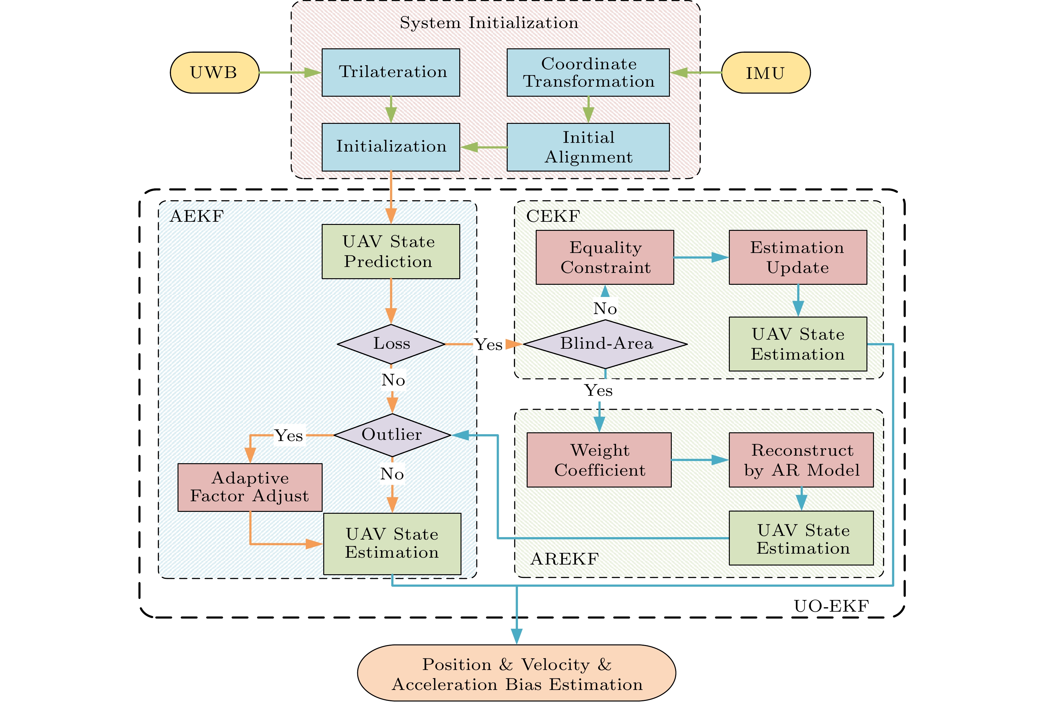
The UAV localization framework is a completed localization solution based on the UAV movement model as shown in Fig.3. The initial UAV position in the three-dimensional space is determined by the trilateration method within the signal coverage of four non-coplanar anchors, while its orientation is manually specified to achieve initial alignment. In the established UAV movement model, IMU is adopted as control inputs, and UWB measurements are used as observations. As described above, UWB signals are unreliable in hostile environments, which inevitably brings intermittent and unreliable UWB ranging, resulting in incorrect or even failed state updates.
Therefore, we first propose the adaptive extended Kalman filter (AEKF) to solve these problems. If the UWB measurement is obtained in the current sampling period, AEKF is performed to detect outliers and further estimate the position, velocity, and acceleration bias. Otherwise, the state estimation of the UAV is obtained by the extended Kalman filter based on the state constraint (CEKF) that considers the equality relation. When UWB measurements are lost in multiple continuous periods, it means that the UAV is in the blind areas of UWB ranging. In this case, the lost measurements can be reconstructed by the auto-regressive model, and the estimation is updated by the extended Kalman filter based on the auto-regressive model (AREKF). Thus, an efficient UAV localization framework is finally formed by integrating the above filtering methods, which is called an extended Kalman filter with unreliable observations (UO-EKF).
3.2 Basic EKF for UAV Localization
For the non-linearity localization systems, EKF shows robust and accurate performance. Based on the above UAV movement model (2) and (3), the predictions of the state and error variance can be obtained by the following equations:
{{\hat{\boldsymbol{x}}}_{k|k - 1}} = {\boldsymbol{A}}_k{{\hat{\boldsymbol{x}}}_{k - 1}} + {\boldsymbol{B}}_{k - 1}{{\boldsymbol{u}}_{k - 1}}, \label{eq16} {\boldsymbol{P}}_{k|k - 1} = {{\boldsymbol{A}}_k}{{\boldsymbol{P}}_{k - 1}}{\boldsymbol{A}}_k^{\rm T} + {{\boldsymbol{Q}}_{k - 1}}. Assume that IMU is interfering with Gaussian noises. Furthermore, {\tau _a} and {\tau _b} represent IMU noises and the uncertainty of acceleration bias, respectively. Thus, the covariance matrix of system noise can be obtained as:
{{\boldsymbol{Q}}_{k-1}} = {\rm{diag}}\left( {{{\boldsymbol{Q}}}'_{k-1},\ {{\boldsymbol{Q}}}'_{k-1},\ {{\boldsymbol{Q}}}'_{k-1}} \right), {{{\boldsymbol{Q}}}'_{k - 1}} = \left( {\begin{array}{*{20}{c}} {{ {\dfrac{{{T^3}{\tau _a}}}{3}}} + { {{\dfrac{{{T^5}{\tau _b}}}{20}}}}}&{{ {\dfrac{{{T^2}{\tau _a}}}{2}}} + { {\dfrac{{{T^4}{\tau _b}}}{8}}}}&{ - { {\dfrac{{{T^3}{\tau _b}}}{6}}}}\\ {{ {\dfrac{{{T^2}{\tau _a}}}{2}}} + { {\dfrac{{{T^4}{\tau _b}}}{8}}}}&{T{\tau _a} + { {\dfrac{{{T^3}{\tau _b}}}{3}}}}&{ - { {\dfrac{{{T^2}{\tau _b}}}{2}}}}\\ { - { {\dfrac{{{T^3}{\tau _b}}}{6}}}}&{ - { {\dfrac{{{T^2}{\tau _b}}}{2}}}}&{T{\tau _b}} \end{array}} \right). According to (3), the predicted range between the mobile UAV and the UWB anchor at time k is:
{{\hat{\boldsymbol{r}}}_{k|k-1}} = h({\hat{\boldsymbol{x}}}_{k|k-1}). Then, the measurement matrix can be obtained by the first-order Taylor expansion:
{\boldsymbol{H}}_k = {\left( {{ {\frac{{{\hat p_{x}} - {p_{Ax}}}}{{{{\hat r}_{k|k-1}}}} }},\,0,\,0,\,{ {\frac{{{\hat p_{y}} - {p_{Ay}}}}{{{{\hat r}_{k|k-1}}}}}},\,0,\,0,\,{ {\frac{{{\hat p_{z}} - {p_{Az}}}}{{{{\hat r}_{k|k-1}}}}}},\,0,\,0} \right)},\, where ( {\hat p_{x}} , {\hat p_{y}} , {\hat p_{z}} ) represents the predicted position of the UAV at time k .
The measurement update of EKF is defined as:
{{\hat{\boldsymbol{x}}}_k} = {{\hat{\boldsymbol{x}}}_{k|k - 1}} + {{\boldsymbol{K}}_k}({{\boldsymbol{r}}_k} - { {\hat{\boldsymbol{r}}}_{k|k-1}}), \label{eq23} {{\boldsymbol{P}}_k} = ({\boldsymbol{I}} - {{\boldsymbol{K}}_k}{{\boldsymbol{H}}_k}){{\boldsymbol{P}}_{k|k - 1}}, \begin{aligned} {{\boldsymbol{K}}_k} = {{\boldsymbol{P}}_{k|k - 1}}{\boldsymbol{H}}_k^{\rm{T}}{({{\boldsymbol{H}}_k}{{\boldsymbol{P}}_{k|k - 1}}{\boldsymbol{H}}_k^{\rm{T}} + {{\boldsymbol{R}}_k})^{ - 1}}, \end{aligned} where the measurement noise covariance {{\boldsymbol{R}}_k} = \sigma _r^2 , and {\sigma _r} represents the measurement uncertainty between the anchor and the mobile UAV.
The EKF based on the fusion of UWB and IMU under the acceleration assumption is introduced in this section. Nevertheless, such traditional EKF is not suitable for UAV localization in the hostile underground environments.
4. AEKF for Measurement Outliers
Due to the impacts of multipath effects and obstructions, the outliers of UWB ranging are inevitable in hostile underground scenarios. Here, AEKF is proposed for abnormal UWB ranging to improve localization accuracy by minimizing the error of the innovation covariance matrix and solving the adaptive factor to adjust the noise covariance matrix. Based on EKF, the innovation {{\boldsymbol{e}}_{k|k - 1}} is defined as:
{{\boldsymbol{e}}_{k|k - 1}} = {{\boldsymbol{r}}_k} - {{\hat{\boldsymbol{r}}}_{k|k-1}}. \label{eq25} Its covariance matrix is:
\begin{aligned}[b] {{\boldsymbol{M}}_{k|k - 1}}& = {\rm{E}}\{ {{\boldsymbol{e}}_{k|k - 1}}{\boldsymbol{e}}_{k|k - 1}^{\rm{T}}\} \\& = {{\boldsymbol{H}}_k}{{\boldsymbol{P}}_{k|k - 1}}{\boldsymbol{H}}_k^{\rm{T}} + {{\boldsymbol{R}}_k} \\&= {{\boldsymbol{H}}_k}{{\boldsymbol{A}}_k}{{\boldsymbol{P}}_{k - 1}}{\boldsymbol{A}}_k^{\rm{T}}{\boldsymbol{H}}_k^{\rm{T}} + {{\boldsymbol{H}}_k}{{\boldsymbol{Q}}_{k - 1}}{\boldsymbol{H}}_k^{\rm{T}} + {{\boldsymbol{R}}_k}. \end{aligned} It can be seen that {{\boldsymbol{M}}_{k|k - 1}} reflects the error variance between the range measurement {{\boldsymbol{r}}_k} and its prediction {{\hat{\boldsymbol{r}}}_{k|k-1}} . Excessive {{\boldsymbol{M}}_{k|k - 1}} means the range measurement may be unreasonable, which should be dynamically adjusted based on the actual noise. In the followings, we give its coping strategy in localization.
The threshold of innovation error variance {\boldsymbol{\varPsi}} \geqslant {\bf{0}} is introduced for outlier detection, and {\boldsymbol{\varPsi}} can be selected according to the actual situation. If the innovation covariance matrix {{\boldsymbol{M}}_{k|k - 1}} \leqslant {\boldsymbol{\varPsi}} , basic EKF is employed. Otherwise, the adaptive factor {\lambda _k} > 0 is introduced to adjust the covariance of the system and measurement noise. Accordingly, the updated innovation covariance matrix { {\bar{\boldsymbol{M}}}_{k|k - 1}} is represented as:
{{\bar{\boldsymbol{M}}}_{k|k - 1}} = {{\boldsymbol{H}}_k}{{\boldsymbol{A}}_k}{{\boldsymbol{P}}_{k - 1}}{\boldsymbol{A}}_k^{\rm{T}}{\boldsymbol{H}}_k^{\rm{T}} + {\lambda _k}({{\boldsymbol{H}}_k}{{\boldsymbol{Q}}_{k - 1}}{\boldsymbol{H}}_k^{\rm{T}} + {{\boldsymbol{R}}_k}). (6) Considering the updated matrix { {\bar{\boldsymbol{M}}}_{k|k - 1}} is a function of {\lambda _k} , the optimal value {\lambda ^*_k} can be obtained by minimizing the following formula:
\min \{ F({\lambda _k}) = {\left\| {{\boldsymbol{\varPsi}} - \bar{\boldsymbol{M}}_{k|k-1}({\lambda _k})} \right\|^2}\}, (7) where {\left\| {\boldsymbol{M}} \right\|^2} is the norm of {\boldsymbol{M}} and {\left\| {{\boldsymbol{M}}} \right\|^2} = {\rm{tr}}({\boldsymbol{M}}{{\boldsymbol{M}}^{\rm{T}}}) .
For convenience, let {\boldsymbol{C}} = {\bar{\boldsymbol{M}}}_{k|k-1} , {\boldsymbol{D}} = {{\boldsymbol{H}}_k}{{\boldsymbol{A}}_k}{\boldsymbol{P}}_{k-1} {\boldsymbol{A}}_k^{\rm{T}}{\boldsymbol{H}}_k^{\rm{T}} , and {\boldsymbol{E}} = {{\boldsymbol{H}}_k}{{\boldsymbol{Q}}_{k - 1}}{\boldsymbol{H}}_k^{\rm{T}} + {{\boldsymbol{R}}_k} . Obviously, (6) can now be rewritten as {\boldsymbol{C}}(\lambda_k) = {\boldsymbol{D}} + \lambda_k {\boldsymbol{E}} . Here we solve \lambda_k according to the similar idea in [27], and the solving procedure of (7) is as follows.
\begin{aligned}[b]F(\lambda _k ) = &\ {\left\| {{\boldsymbol{\varPsi}} - {\boldsymbol{D}} - \lambda _k {\boldsymbol{E}}} \right\|^2} \\= &\ {\rm{tr}}\{ ({\boldsymbol{\varPsi}} - {\boldsymbol{D}} - \lambda _k {\boldsymbol{E}}){({\boldsymbol{\varPsi}} - {\boldsymbol{D}} - \lambda _k {\boldsymbol{E}})^{\rm{T}}}\} \\ = &\ \lambda^2_k {\rm{tr}} \{{\boldsymbol{E}}{\boldsymbol{E}}^{\rm{T}}\} - 2\lambda _k{\rm{tr}} \{({\boldsymbol{\varPsi}} - {\boldsymbol{D}}){\boldsymbol{E}}^{\rm{T}} \}+ \\&\ {\rm{tr}}\{ ({\boldsymbol{\varPsi}} - {\boldsymbol{D}}){({\boldsymbol{\varPsi}} - {\boldsymbol{D}})^{\rm{T}}}\}. \end{aligned} The necessary condition for \lambda^*_k to yield a minimum of F(\lambda_k) is {\rm d}F(\lambda_k)/d\lambda_k = 0 , which gives
\begin{array}{l} \dfrac{{{\rm d}F(\lambda_k)}}{{\rm d}\lambda_k} = 2\lambda_k {\rm{tr}}\{{\boldsymbol{E}}{{\boldsymbol{E}}^{\rm{T}}}\}- 2 {\rm{tr}}\{ ({\boldsymbol{\varPsi}} -{\boldsymbol{D}}){{\boldsymbol{E}}^{\rm{T}}}\} = 0. \end{array} Thus, one can easily get the optimal solution:
{\lambda ^*_k} = \frac{{{\rm{tr}}\{ ({\boldsymbol{\varPsi}} - {\boldsymbol{D}}){{\boldsymbol{E}}^{\rm{T}}}\} }}{{{\rm{tr}}\{{\boldsymbol{E}}{{\boldsymbol{E}}^{\rm{T}}}\}}}, {\boldsymbol{E}} \ne {\bf{0}}. And it can be further expressed as:
\lambda _k^* = \frac{{{\rm{tr}}\{ ({\boldsymbol{\varPsi}} - {{\boldsymbol{H}}_k}{{\boldsymbol{A}}_k}{\boldsymbol{P}}_{k-1}{\boldsymbol{A}}_k^{\rm{T}}{\boldsymbol{H}}_k^{\rm{T}})({{\boldsymbol{H}}_k}{{\boldsymbol{Q}}_{k - 1}}{\boldsymbol{H}}_k^{\rm{T}} + {{\boldsymbol{R}}_k})^{\rm{T}}\} }}{{{\rm{tr}}\{ ({{\boldsymbol{H}}_k}{{\boldsymbol{Q}}_{k - 1}}{\boldsymbol{H}}_k^{\rm{T}} + {{\boldsymbol{R}}_k})({{\boldsymbol{H}}_k}{{\boldsymbol{Q}}_{k - 1}}{\boldsymbol{H}}_k^{\rm{T}} + {{\boldsymbol{R}}_k})^{\rm{T}}\} }}. \label{eq33} Accordingly, the updated innovation covariance matrix is as follows:
{\bar{\boldsymbol{M}}}_{k|k - 1}^{\rm{*}} = {{\boldsymbol{H}}_k}{{\boldsymbol{A}}_k}{{\boldsymbol{P}}_{k - 1}}{\boldsymbol{A}}_k^{\rm{T}}{\boldsymbol{H}}_k^{\rm{T}} + \lambda _k^*({{\boldsymbol{H}}_k}{{\boldsymbol{Q}}_{k - 1}}{\boldsymbol{H}}_k^{\rm{T}} + {{\boldsymbol{R}}_k}). \label{eq34} Finally, we implement the proposed adaptive extended Kalman filter.
5. Localization with Measurement Loss
Two improvements based on EKF are proposed in this section. The first improves the accuracy of UAV localization by constraining the state when the intermittent loss of UWB measurements occurs. The second reconstructs continuous lost measurements when the UAV flies in the blind areas of UWB ranging, and then AEKF is adopted to deal with the inaccurate measurement reconstructed by the auto-regressive model.
5.1 CEKF for Intermittent Measurement Loss
The severe obstruction and interference of large equipments in hostile underground environments may lead to the failure of UWB-ranging or even long-term failures. A binary random variable \eta _k is introduced to represent whether the UWB measurement is lost or not at k time. If \eta _{k} = 0 , it indicates that the range measurement is lost. Otherwise, the range measurement is successfully received. Let us assume \eta _k is an independent and identically distributed (i.i.d.) Bernoulli variable and p(\eta _{k} = 0) = \theta . Together with (3), it yields that:
{{\boldsymbol{r}}_k} = \eta _{k}h({{\boldsymbol{x}}_k}) + {{\boldsymbol{v}}_k}. \label{eq36} Correspondingly, the state estimation {\hat{\boldsymbol{x}}}_k and the error covariance {{\boldsymbol{P}}_k} can be described as below:
{ {\hat{\boldsymbol{x}}}_k} = { {\hat{\boldsymbol{x}}}_{k|k - 1}} + {\eta _k}{{\boldsymbol{K}}_k}({{\boldsymbol{r}}_k} - { {\hat{\boldsymbol{r}}}_{k|k-1}}), {{\boldsymbol{P}}_k} = ({\boldsymbol{I}} - {\eta _k}{{\boldsymbol{K}}_k}{{\boldsymbol{H}}_k}){{\boldsymbol{P}}_{k|k - 1}}. The above method called Open-Loop Kalman Filter (OLKF), is a classic strategy to solve the issue of measurement loss. However, it does not perform measurement updates when \eta _{k} = 0 . Although OLKF is a simple and fast method to deal with measurement loss, the localization performance of OLKF is unsatisfactory in the underground environments.
Therefore, CEKF is proposed to improve the accuracy while the range measurements are accidentally lost by projecting unconstrained state estimation onto the constraint plane and transforming it into a minimization problem. Generally speaking, the state vectors often satisfy some kind of equality relation, and adding the corresponding equality constraint can improve estimation accuracy. In actual localization, because of the high sampling frequency of UWB, the innovations in adjacent sampling periods are close. Without loss of generality, we give the following state constraint:
{{\boldsymbol{H}}_k}{{\boldsymbol{x}}_k} - {{\boldsymbol{H}}_k}{ {\hat{\boldsymbol{x}}}_{k|k-1}} \leqslant {\boldsymbol{d}}_{k-1}, where {\boldsymbol{d}}_{k-1} = {{\boldsymbol{r}}_{k-1}} - { {\hat{\boldsymbol{r}}}_{k-1|k-2}} is the innovation of the last sampling period. In other words, the system state of the UAV should meet (8) at least:
{{\boldsymbol{H}}_k}{{\boldsymbol{x}}_k} - {{\boldsymbol{H}}_k}{ {\hat{\boldsymbol{x}}}_{k|k-1}} = {\boldsymbol{d}}_{k-1}. (8) We directly project the unconstrained state estimate {\hat{\boldsymbol{x}}}_k onto the constraint plane (8) when the range measurement is lost. The constrained state estimation {\bar{\boldsymbol{x}}}_k is the projection of {\hat{\boldsymbol{x}}}_k . Thus, {\bar{\boldsymbol{x}}}_k satisfies the following equations:
{ {\bar{\boldsymbol{x}}}_k} = {\rm{min}}_{ {\bar{\boldsymbol{x}}}_k} \{ {( {\bar{\boldsymbol{x}}}_k - {\hat{\boldsymbol{x}}}_k)^{\rm{T}}}{\boldsymbol{W}}( {\bar{\boldsymbol{x}}}_k - {\hat{\boldsymbol{x}}}_k)\}, {{\boldsymbol{H}}_k}{{\bar{\boldsymbol{x}}}_k} = {\boldsymbol{d}}_{k-1} + { {\hat{\boldsymbol{r}}}_{k|k-1}}, where { {\hat{\boldsymbol{r}}}_{k|k-1}} = {{\boldsymbol{H}}_k}{ {\hat{\boldsymbol{x}}}_{k|k-1}} , and {\boldsymbol{W}} is a positive definite matrix. The expression L with the Lagrange operator and the necessary conditions for its minimization are given as follows:
\begin{aligned}[b] & L = {({ {\bar{\boldsymbol{x}}}_k} - { {\hat{\boldsymbol{x}}}_k})^{\rm{T}}}{\boldsymbol{W}}({ {\bar{\boldsymbol{x}}}_k} - { {\hat{\boldsymbol{x}}}_k})\; +\\&\qquad\ \ 2{{\boldsymbol{S}}_k^{\rm{T}}}({{\boldsymbol{H}}_k}{ {\bar{\boldsymbol{x}}}_k} - { {\hat{\boldsymbol{r}}}_{k|k-1}} - {\boldsymbol{d}}_{k-1}), \\&\dfrac{{\partial L}}{{\partial {\bar{\boldsymbol{x}}}_k}} = {\boldsymbol{W}}({ {\bar{\boldsymbol{x}}}_k} - { {\hat{\boldsymbol{x}}}_k}) + {\boldsymbol{H}}_k^{\rm{T}}{\boldsymbol{S}}_k = {\bf{0}}, \\& \dfrac{{\partial L}}{{\partial {\boldsymbol{S}}_k}} = {{\boldsymbol{H}}_k}{ {\bar{\boldsymbol{x}}}_k} - { {\hat{\boldsymbol{r}}}_{k|k-1}} - {\boldsymbol{d}}_{k-1} = {\bf{0}}, \end{aligned} where {\boldsymbol{S}}_k is the Lagrange operator. From the above formulas, one can easily get the solution:
{{\boldsymbol{S}}_k} = {({{\boldsymbol{H}}_k}{{\boldsymbol{W}}^{ - 1}}{\boldsymbol{H}}_k^{\rm{T}})^{ - 1}}({{\boldsymbol{H}}_k}{{\hat{\boldsymbol{x}}}_k} - { {\hat{\boldsymbol{r}}}_{k|k-1}} - {\boldsymbol{d}}_{k-1}), (9) { {\bar{\boldsymbol{x}}}_k} = { {\hat{\boldsymbol{x}}}_k} - {{\boldsymbol{W}}^{ - 1}}{{\boldsymbol{H}}_k^{\rm{T}}}{{\boldsymbol{S}}_k}. (10) Particularly, it is the least mean square error method if {\boldsymbol{W}} = {\boldsymbol{I}} . When {\boldsymbol{W}} = {{\boldsymbol{P}}^{ - 1}_{k}} , it degenerates into the maximum likelihood estimation method.
According to (9) and (10), the following equation can be easily got:
\begin{array}{l} \; \; \; \; {{\boldsymbol{x}}_k} - { {\bar{\boldsymbol{x}}}_k} \\ = {{\boldsymbol{x}}_k} - { {\hat{\boldsymbol{x}}}_k} + {{\boldsymbol{W}}^{ - 1}}{\boldsymbol{H}}_k^{\rm{T}}{({{\boldsymbol{H}}_k}{{\boldsymbol{W}}^{ - 1}}{\boldsymbol{H}}_k^{\rm{T}})^{ - 1}}({{\boldsymbol{H}}_k}{ {\hat{\boldsymbol{x}}}_k} - {{\boldsymbol{H}}_k}{\boldsymbol{x}}_k) \\ = ({\boldsymbol{I}} - {{\boldsymbol{W}}^{ - 1}}{\boldsymbol{H}}_k^{\rm{T}}{({{\boldsymbol{H}}_k}{{\boldsymbol{W}}^{ - 1}}{\boldsymbol{H}}_k^{\rm{T}})^{ - 1}}{{\boldsymbol{H}}_k})({{\boldsymbol{x}}_k} - { {\hat{\boldsymbol{x}}}_k}) \\ = {{\boldsymbol{\Gamma}} _k}({{\boldsymbol{x}}_k} - { {\hat{\boldsymbol{x}}}_k}), \end{array} where {{\boldsymbol{\Gamma}} _k} = {\boldsymbol{I}} - {{\boldsymbol{W}}^{ - 1}}{\boldsymbol{H}}_k^{\rm{T}}{({{\boldsymbol{H}}_k}{{\boldsymbol{W}}^{ - 1}}{\boldsymbol{H}}_k^{\rm{T}})^{ - 1}}{{\boldsymbol{H}}_k} . Considering that {{\boldsymbol{\Gamma}}_{\boldsymbol{k}}} and {\boldsymbol{x}}_k are independent of each other, we obtain the covariance matrix of estimation error {{\bar{\boldsymbol{P}}}}_k :
\begin{aligned}[b] { {\bar{\boldsymbol{P}}}_k} &= {\rm{E}}\{ ({{\boldsymbol{x}}_k} - { {\bar{\boldsymbol{x}}}_k}){({{\boldsymbol{x}}_k} - { {\bar{\boldsymbol{x}}}_k})^{\rm{T}}}\} \\&= {{\boldsymbol{\Gamma}} _k}{\rm{E}}\{ ({{\boldsymbol{x}}_k} - { {\hat{\boldsymbol{x}}}_k}){({{\boldsymbol{x}}_k} - { {\hat{\boldsymbol{x}}}_k})^{\rm{T}}}\} {\boldsymbol{\Gamma}} _k^{\rm{T}} \\&= {{\boldsymbol{\Gamma}} _k}{{\boldsymbol{P}}_k}{\boldsymbol{\Gamma}} _k^{\rm{T}}. \end{aligned} Till now, we have finished the CEKF derivation for intermittent measurement losses.
5.2 AREKF for Continuous Measurement Loss
Although the performance of CEKF is better than that of OLKF, it still cannot provide satisfactory performance for the continuous losses of range measurements when the UAV is in the range blind area. The auto-regressive model is a promising scheme that can compensate for the lost measurements in the process of state estimation[31, 32]. Inspired by this, AREKF is proposed based on the auto-regressive compensation scheme, in which the compensated UWB range measurement at time k is expressed as:
{ {\bar{\boldsymbol{r}}}_k} = \sum\limits_{i = 1}^p {{\alpha _i}{{\boldsymbol{r}}_{k,\ i}}}, \label{eq56} where { {\bar{\boldsymbol{r}}}_k} is the reconstructed measurement. {{\boldsymbol{r}}_{k,i}} is the latest i -th observation stored in memory, p is the observation number which is determined according to actual situations, and {\alpha _i} is the linear weight coefficient.
The output error of the compensated observation vector is further defined as follows:
{{\boldsymbol{e}}_r}(k){\rm{ = }}{{\boldsymbol{r}}_k} - { {\bar{\boldsymbol{r}}}_k}. \label{eq57} Consequently, the weight {\alpha _i} can be obtained by minimizing the following formula:
{{\boldsymbol{J}}_k} = {\rm{E}}\{ {{\boldsymbol{e}}_r}(k){\boldsymbol{e}}_r^{\rm{T}}(k)\} = {\rm{E}}\{ ({{\boldsymbol{r}}_k} - { {\bar{\boldsymbol{r}}}_k}){({{\boldsymbol{r}}_k} - { {\bar{\boldsymbol{r}}}_k})^{\rm{T}}}\}. \label{eq58} According to [33], we calculate the value of \alpha_i by:
\frac{{\partial {{\boldsymbol{J}}_k}}}{{\partial {\alpha _i}}} = {\rm{E}}\left\{ {\frac{{\partial {{\boldsymbol{J}}_k}}}{{\partial {{ {\bar{\boldsymbol{r}}}}_k}}}\frac{{\partial {{ {\bar{\boldsymbol{r}}}}_k}}}{{\partial {\alpha _i}}}} \right\} = {\rm{E}}\{ 2({{\boldsymbol{r}}_k} - { {\bar{\boldsymbol{r}}}_k}){\boldsymbol{r}}_{k,\ i}^{\rm{T}}\} {\rm{ = }}{\bf{0}}. (11) Furthermore, (11) is rewritten as a linear system consisting of p equations:
\left\{ {\begin{array}{*{20}{c}} {\displaystyle\sum\limits_{i = 1}^p {{\alpha _i}{\rm{E}}\{ {{\boldsymbol{r}}_{k,\ i}}{\boldsymbol{r}}_{k,\ 1}^{\rm{T}}\} = {\rm{E}}\{ {{\boldsymbol{r}}_k}{\boldsymbol{r}}_{k,\ 1}^{\rm{T}}\} } },\\ {\displaystyle\sum\limits_{i = 1}^p {{\alpha _i}{\rm{E}}\{ {{\boldsymbol{r}}_{k,\ i}}{\boldsymbol{r}}_{k,\ 2}^{\rm{T}}\} = {\rm{E}}\{ {{\boldsymbol{r}}_k}{\boldsymbol{r}}_{k,\ 2}^{\rm{T}}\} } },\\ \vdots \\ {\displaystyle\sum\limits_{i = 1}^p {{\alpha _i}{\rm{E}}\{ {{\boldsymbol{r}}_{k,\ i}}{\boldsymbol{r}}_{k,\ p}^{\rm{T}}\} = {\rm{E}}\{ {{\boldsymbol{r}}_k}{\boldsymbol{r}}_{k,\ p}^{\rm{T}}\} } }. \end{array}} \right. (12) Obviously, the optimal value of {\boldsymbol{\alpha}} = {\left( {{\alpha _1},\ {\alpha _2},\ \ldots, {\alpha _p}} \right)^{\rm{T}}} can be obtained by solving (12).
After the lost observation is reconstructed by vector {\bar{\boldsymbol{r}}}_k , AEKF is called to detect and refine the reconstructed value in the proposed AREKF. The state estimation can be expressed as:
{ {\hat{\boldsymbol{x}}}_k} = {{\hat{\boldsymbol{x}}}_{k|k - 1}} + {{\boldsymbol{K}}_k}({ {\bar{\boldsymbol{r}}}_k} - { {\hat{\boldsymbol{r}}}_{k|k-1}}). \label{eq69} At last, we have a decision-making problem left, that is, how to define continuous loss and when to execute AREFK. Here a threshold of the measurement lost time d is introduced. When the number of measurement losses exceeds d , AREKF is invoked. Otherwise, we adopt CEKF for intermittent measurements. The value of d is determined by the practical requirements. Moreover, we will give guidelines about the threshold d through simulations. Combined with the proposed algorithms AEKF, CEKF, and AREKF, we form the overall localization framework.
6. Simulations and Experiments
In this section, the performance of the proposed localization framework is evaluated by simulations and experiments. We first compare UO-EKF with the recent work Fusion EKF[26] and UKF[15] under different parameters in the Gazebo platform[34]. Then, we compare UO-EKF with the classical EKF only with UWB (EKF-UWB)[35], Fusion EKF, UKF, and ESKF[34] in an underground garage and an underground coal mine to verify the practical effect, where ESKF is the recent solution in the coal mine environment.
6.1 Simulations in the Gazebo Platform
We utilize the Gazebo platform to simulate the UAV localization. Gazebo is a simulation platform of the robot operating system (ROS), which can provide the ground truth required for localization.
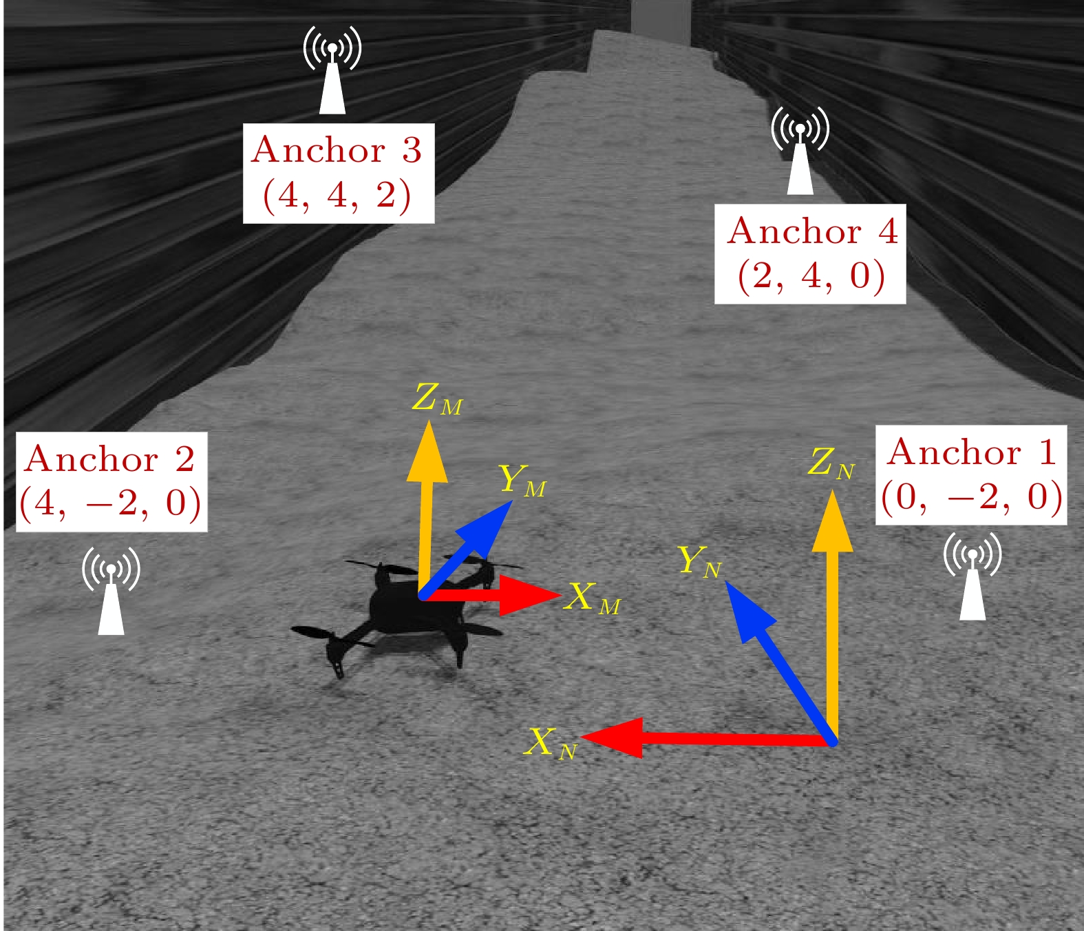
As shown in Fig.4, four non-coplanar anchors are placed at (0, - 2, 0), (4, -2 , 0), (4, 4, 2), and (2, 4, 0), respectively, where the unit of coordinates is meters. The detailed sensor parameters adopted in simulations can be seen in Table 1, where the sampling frequency of the UWB and IMU sensors are 50 Hz and 100 Hz. respectively. The UWB node and the IMU sensor are attached to the UAV, whose maximum linear and angular velocities are 1 m/s and 0.6 rad/s, respectively.
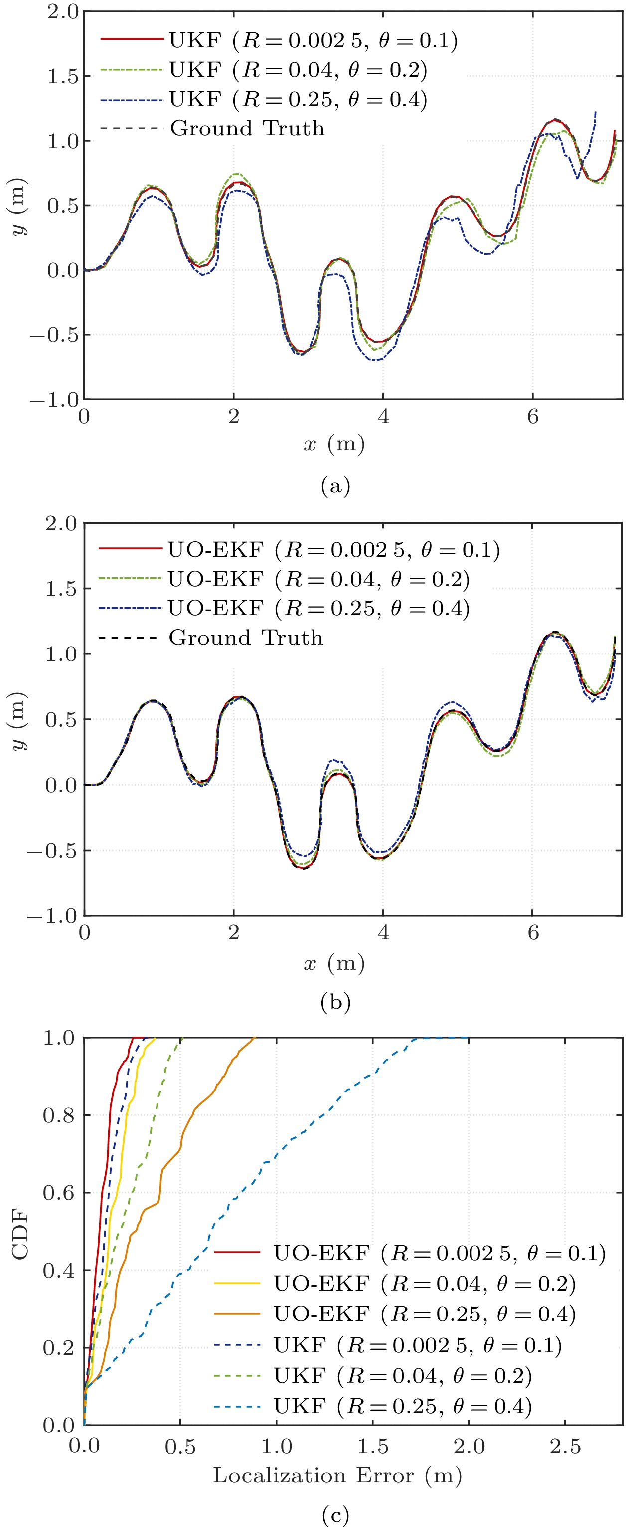
Table 1. Parameters in SimulationsParameter Value Gyroscope noise ( {^{\circ}/{\rm{s}}}) 0.2\times10^{-3} Acceleration noise ( {{\mu}{\rm{g}}}) 1.6\times10^{-2} Gyroscope random walk ({^{\circ}/ {\rm{h}}}) 8.0\times10^{-6} Acceleration random walk ({{\mu}{\rm{g}}}) 0.1\times10^{-2} UWB frequency (Hz) 5.0\times10^{1} IMU frequency (Hz) 1.0\times10^{2} First, we demonstrate the performance of UKF and UO-EKF in terms of the trajectory and CDF with various parameters in Fig.5. The values of UWB parameters including the observation noise {{R}} and loss rate \theta are empirical values obtained by analyzing extensive observations collected in the underground garages and the coal mines during the early ranging experiments. By comparing Fig.5(a) and Fig.5(b), we can see that the trajectory generated by UO-EKF is closer to the ground truth. With the increase of observation noise and loss rate, both UKF and UO-EKF have certain performance degradation. Nevertheless, UO-EKF offers a preferable accuracy even in severe conditions with {{R}} = 0.25 and \theta = 0.4 , as shown in Fig.5(b). It can be seen that UO-EKF almost eliminates the localization delay.
In Fig.5(c), the CDF of localization errors for UKF and UO-EKF is illustrated. Specifically, when {{R}} = 0.002\;5 and \theta = 0.1 , the maximum and average localization errors of the UKF are 0.41 m and 0.19 m, respectively. For UO-EKF, the corresponding errors are 0.36 m and 0.16 m, respectively. The localization accuracy has been improved by about 15.8%. When {{R}} = 0.25 and \theta = 0.4 , the average localization errors of UKF and UO-EKF are about 0.58 m and 0.31 m, respectively. The performance promotion is up to 46.6%, which shows that the larger the observation noise and the loss rate, the greater the performance improvement of UO-EKF.
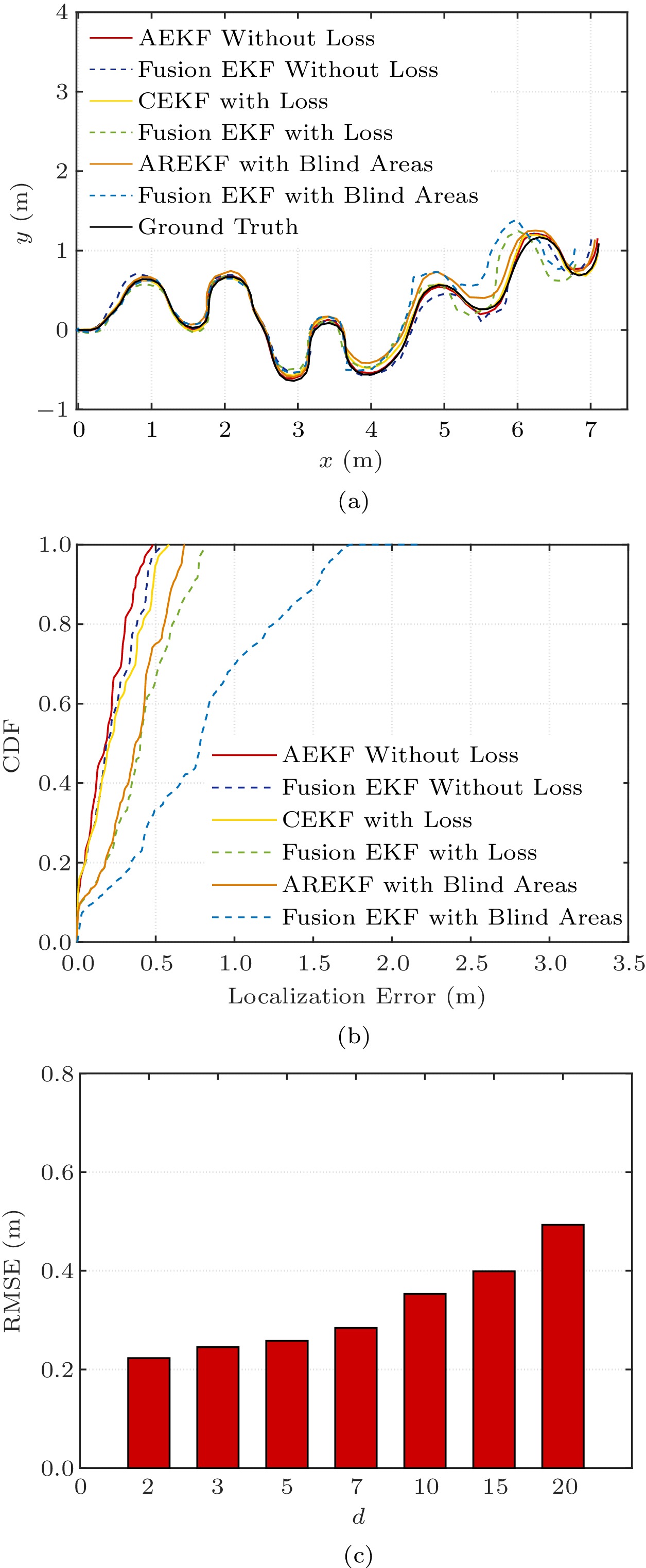
Moreover, we compare the proposed three algorithms, AEKF, CEKF, and AREKF, with Fusion EKF. As shown in Fig.6(a), the trajectory obtained by AEKF is closer to the ground truth than Fusion EKF without the loss of UWB measurements. The UAV localization accuracy of AEKF has been improved to 0.13 m by calculation. Similarly, CEKF and AREKF show better performance than Fusion EKF when the UWB measurement is lost or even when the UAV is in the blind areas. The CDF of localization errors is further shown in Fig.6(b). Solved according to Lagrange's theorem, the localization accuracy of CEKF outperforms Fusion EKF by more than 25%. Specifically, all errors are less than 0.7 m for AREKF in the blind areas, while the corresponding CDF is only 40% for Fusion EKF.
As described above, if the number of measurement losses does not exceed threshold d , CEKF is performed. Otherwise, AREKF is invoked. Fig.6(c) illustrates the impact of loss time d on UO-EKF localization accuracy. When the loss time d is smaller than 5 , the root mean square error (RMSE) basically keeps the same. As the loss time d continues to increase, the RMSE has an obvious increment and it is up to 0.492 m when d = 20 . The results confirm that, although CEKF is simple and efficient, it may not well deal with five or more continuous measurement losses. Therefore, the threshold d can be set as 5 in this simulation, while we can adjust d based on actual conditions in practical applications.
6.2 Experiments in Underground Garage
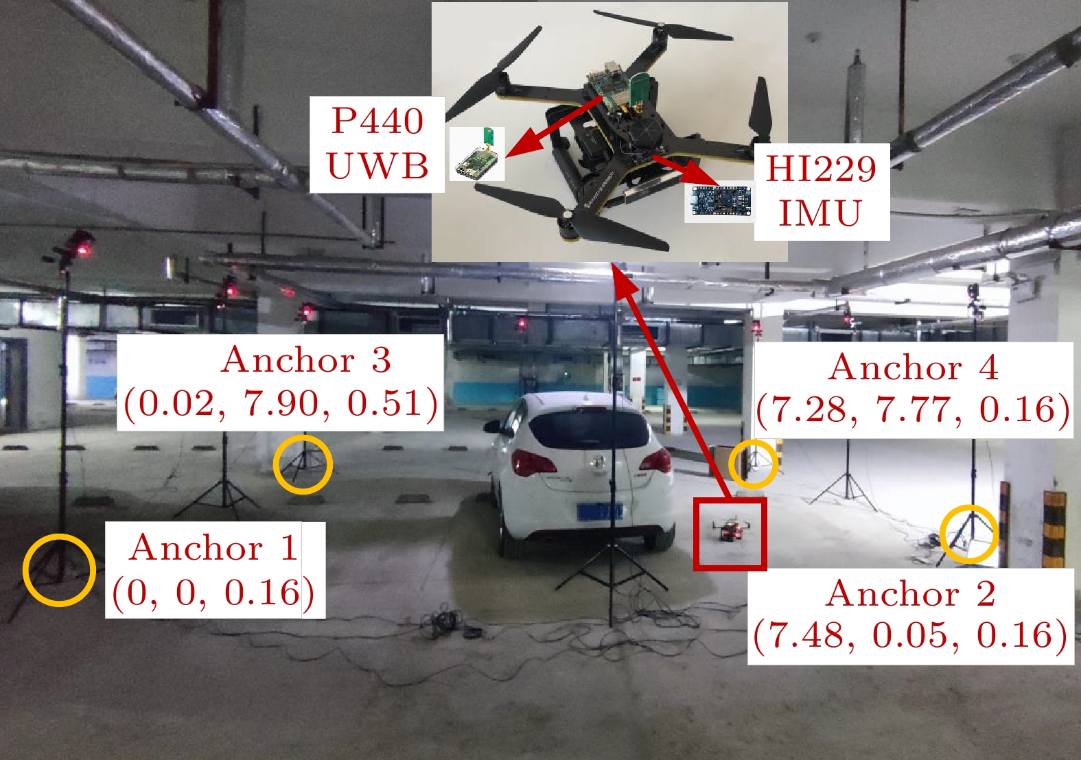
In this subsection, we perform experiments in an underground garage to verify the feasibility of our framework. For the complex underground garages, there are numerous obstacles (vehicles, pipes, and concrete structures) as illustrated in Fig.7. We establish the UAV localization coordinate system through accurate ranging and azimuth measuring. Four non-coplanar anchors are placed at (0, 0, 0.16), (7.48, 0.05, 0.16), (0.02, 7.90, 0.51), (7.28, 7.77, 0.16), respectively, where the coordinates are in meters. The UAV is equipped with a P440 UWB node and a HI229 IMU sensor, and the setup parameters are shown in Table 2. Since the ground truth of localization cannot be obtained directly in experiments, the NOKOV motion capture system with eight cameras is utilized to provide a 100 Hz sampling frequency of ground truth.
Table 2. Parameters in Underground Garage ExperimentsParameter Value Gyroscope noise ( {^{\circ}/{\rm{s}}/{\rm{g}}}) 0.1000 Acceleration noise ({{\rm{g}}/{\sqrt{{\rm{Hz}}}}}) 0.0015 Gyroscope random walk ( {^{\circ}/{\rm{s}}}) 1.0000 Acceleration random walk (g) 0.0300 UWB frequency (Hz) 50.0000 IMU frequency (Hz) 100.0000 UWB variance ( {\rm{m}}^2) 0.0036 After calibrating the UWB sensors and initial alignment of IMU, we conduct the UAV localization experiments in the underground garage, in which the maximum linear velocity and angular velocity are set to 1 m/s and 0.5 rad/s, respectively. Under the above configurations, the flight range of the UAV is about 30 m, and the flight time is about 70 s. It is pointed out that the loss rate of UWB ranging in this experiment is 16.8% by post-measurement statistics.
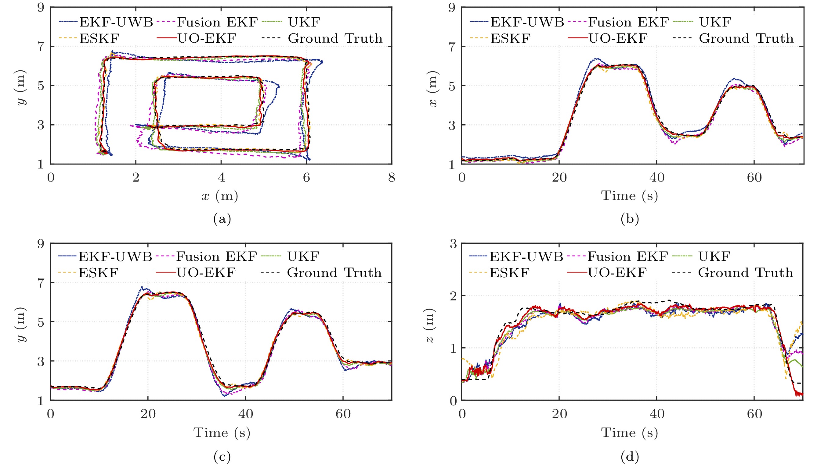
UO-EKF is compared with EKF-UWB[35], Fusion EKF[26], UKF[15], and ESKF[34]. The ground truth and estimated trajectory are illustrated in Fig.8(a). It can be seen that the performance of UO-EKF is obviously better than those of other algorithms. To further describe the performances of these algorithms, Figs.8(b)–8(d) show the positions of the x -axis, y -axis, and z -axis in the localization coordinate system, respectively. Although the accuracy has an inevitable degradation on the corner of the x - y plane for all algorithms, UO-EKF can still achieve excellent performance. In the z -axis direction, the trajectory of UO-EKF is also nearer to the ground truth, especially when the UAV takes off and lands.
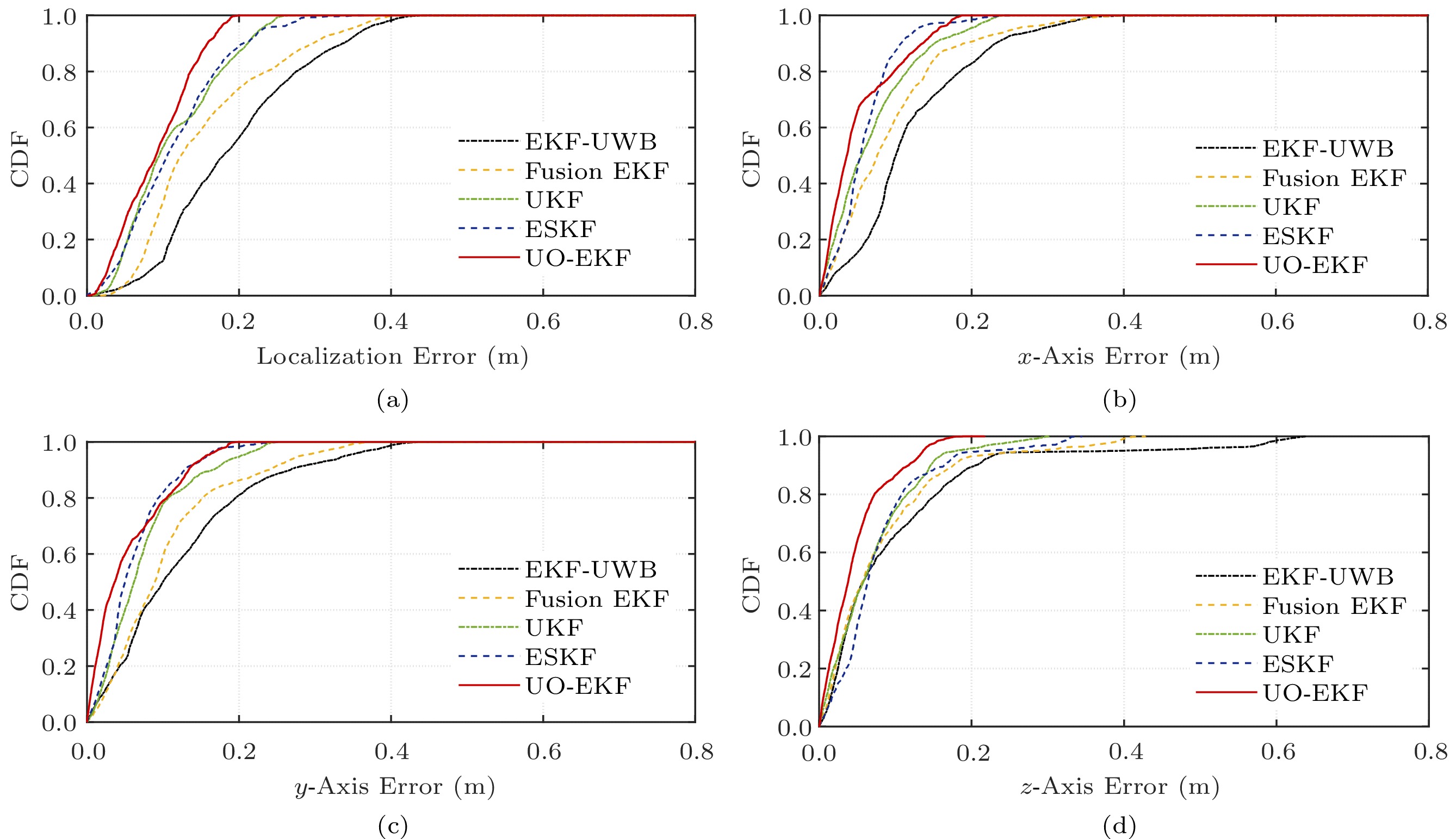
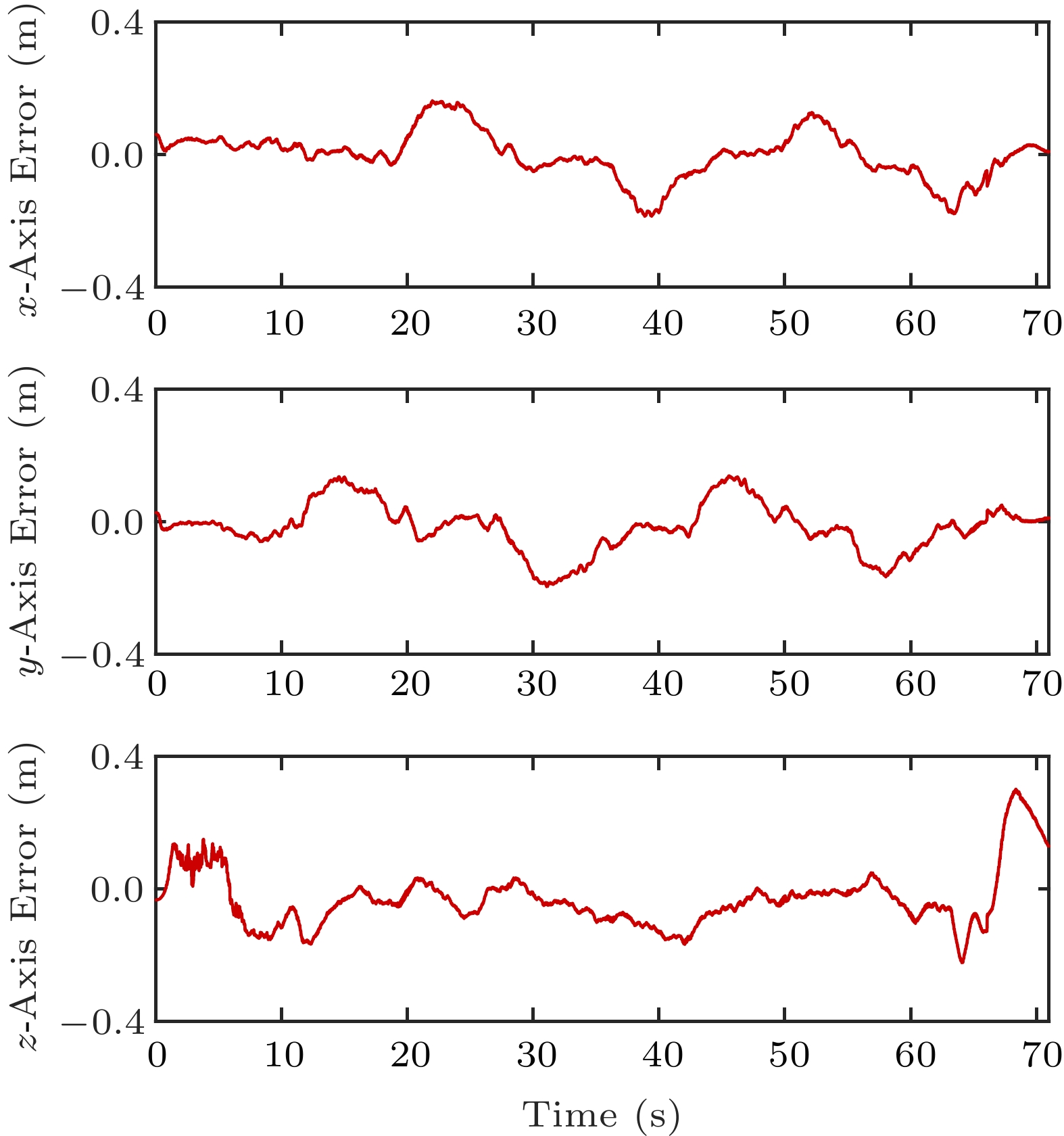
The CDF of localization errors with the aforementioned four algorithms and UO-EKF is shown in Fig.9. It is clear that UO-EKF shows the best performance among all algorithms. For UO-EKF, about 80\% localization errors are less than 0.2 m, and errors are not larger than 0.3 m. The detailed position errors on three axes are illustrated in Fig.10. At last, the RMSE values of all the above algorithms are presented in Table 3, which illustrates that UO-EKF has better robustness and localization accuracy with RMSE 0.192 m in the underground garage. In the following subsection, we further conduct the localization experiments in a realistic coal mine environment.
6.3 Experiments in Coal Mine
As described in Subsection 2.1, the underground coal mine is a typical hostile underground environment, which subjects to serious multipath effects and various noise interference. These factors make the increase of outliers and the loss of UWB range measurements. Due to the limited and fixed scope of the underground monitoring system, it is difficult to satisfy the dynamic monitoring requirements. When there is a temporary demand or problem in coal mine production, it is essential to carry out rapid environmental parameter monitoring and video patrol in local areas.
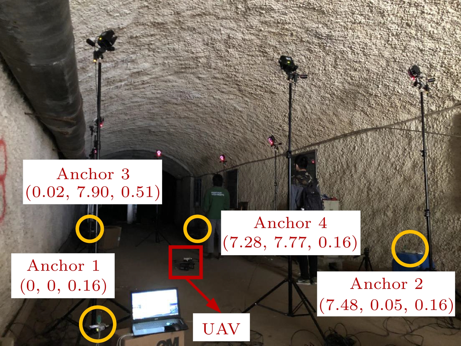
To verify the practicability and effectiveness, the UAV that we independently control in a coal mine can take corresponding measures and quickly enter the designated area to complete monitoring and other tasks. The trajectory of the UAV is an approximate S -shape. The initial setting of IMU is aligned with the localization coordinate system. Moreover, its intrinsic parameters are still consistent with those in the underground garage. Besides, four UWB anchors are fixed in the tunnel, as shown in Fig.11. In the given coal mine experiment environment, the ranging error variance is about
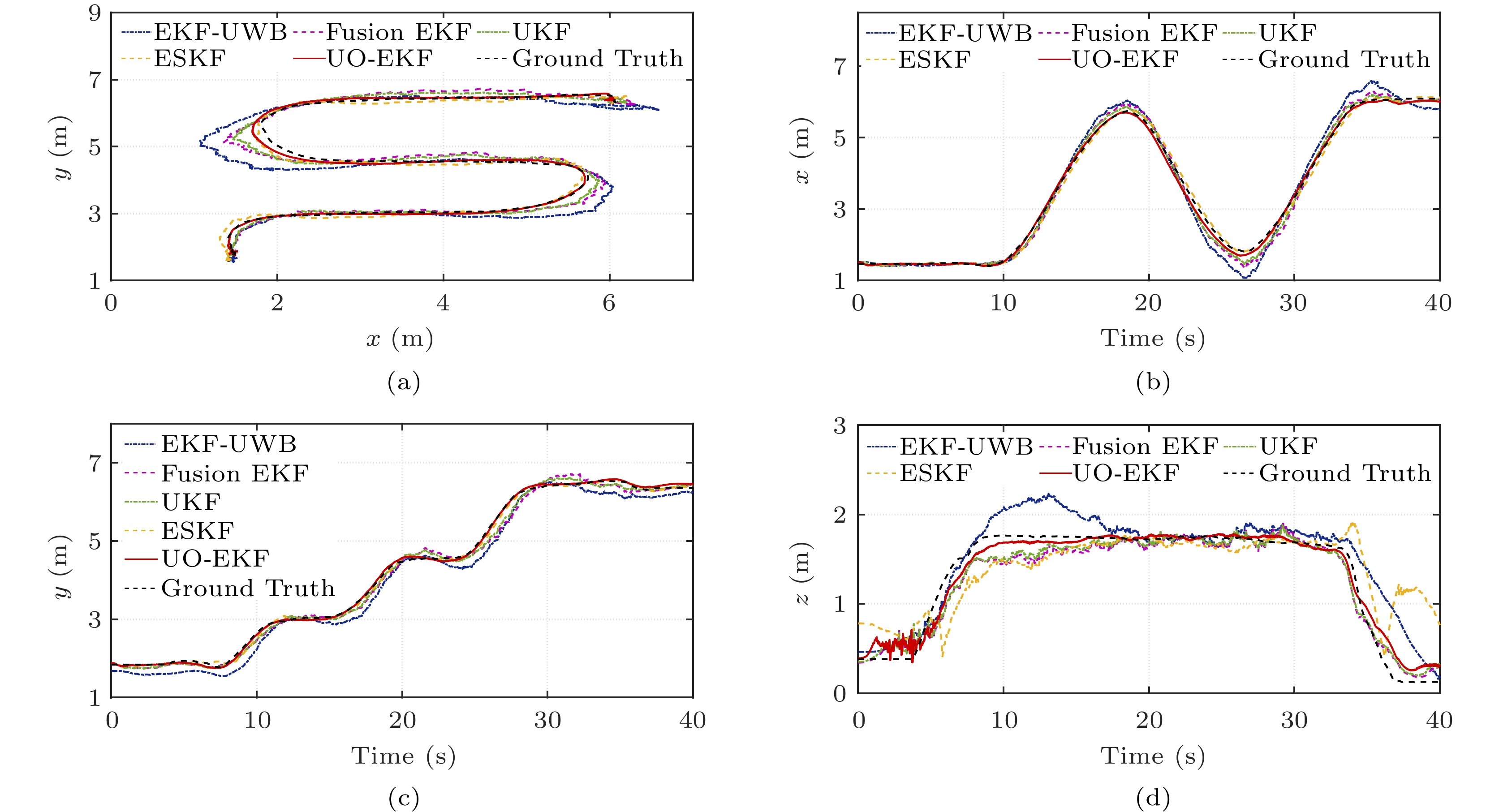
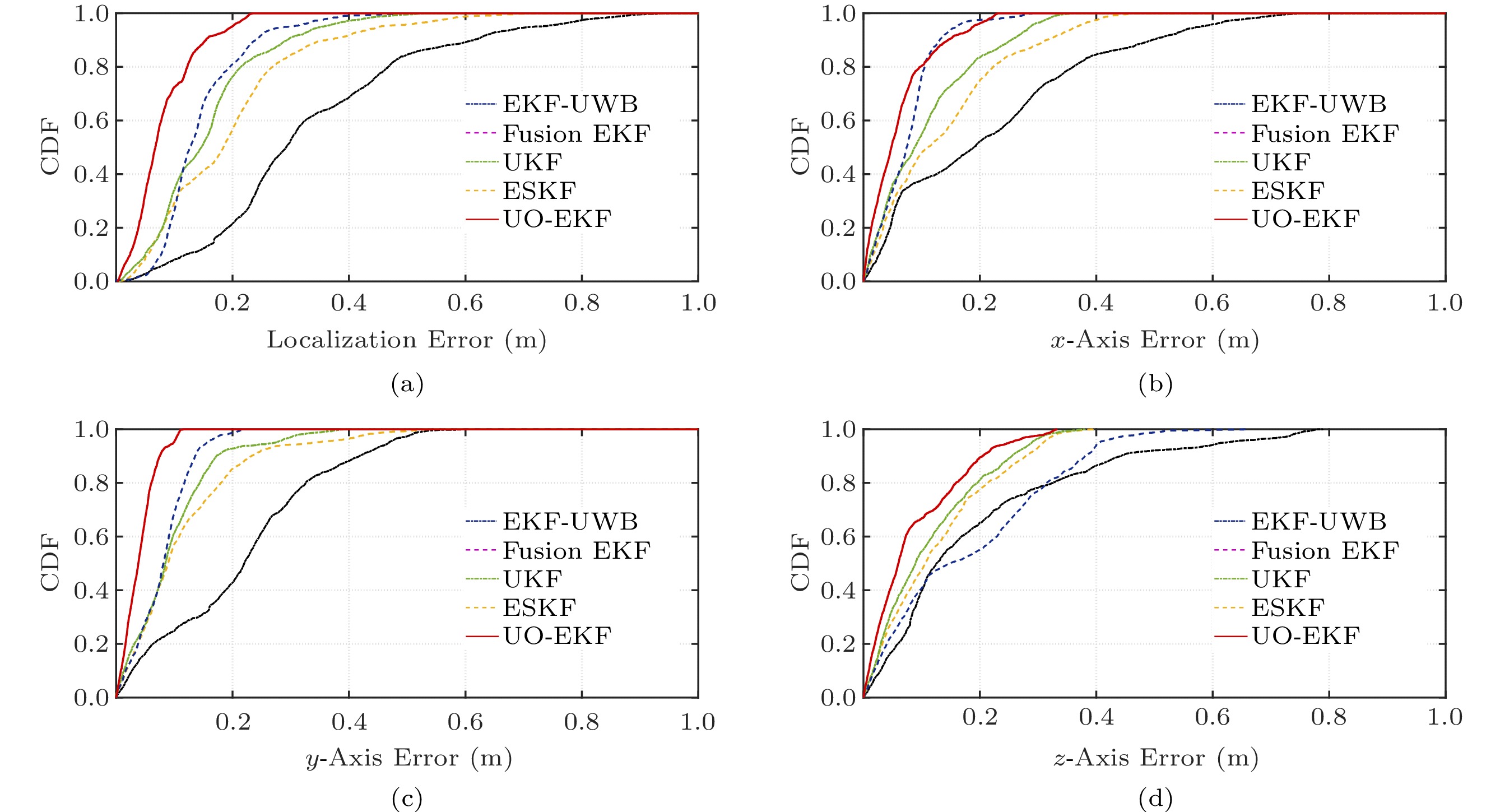
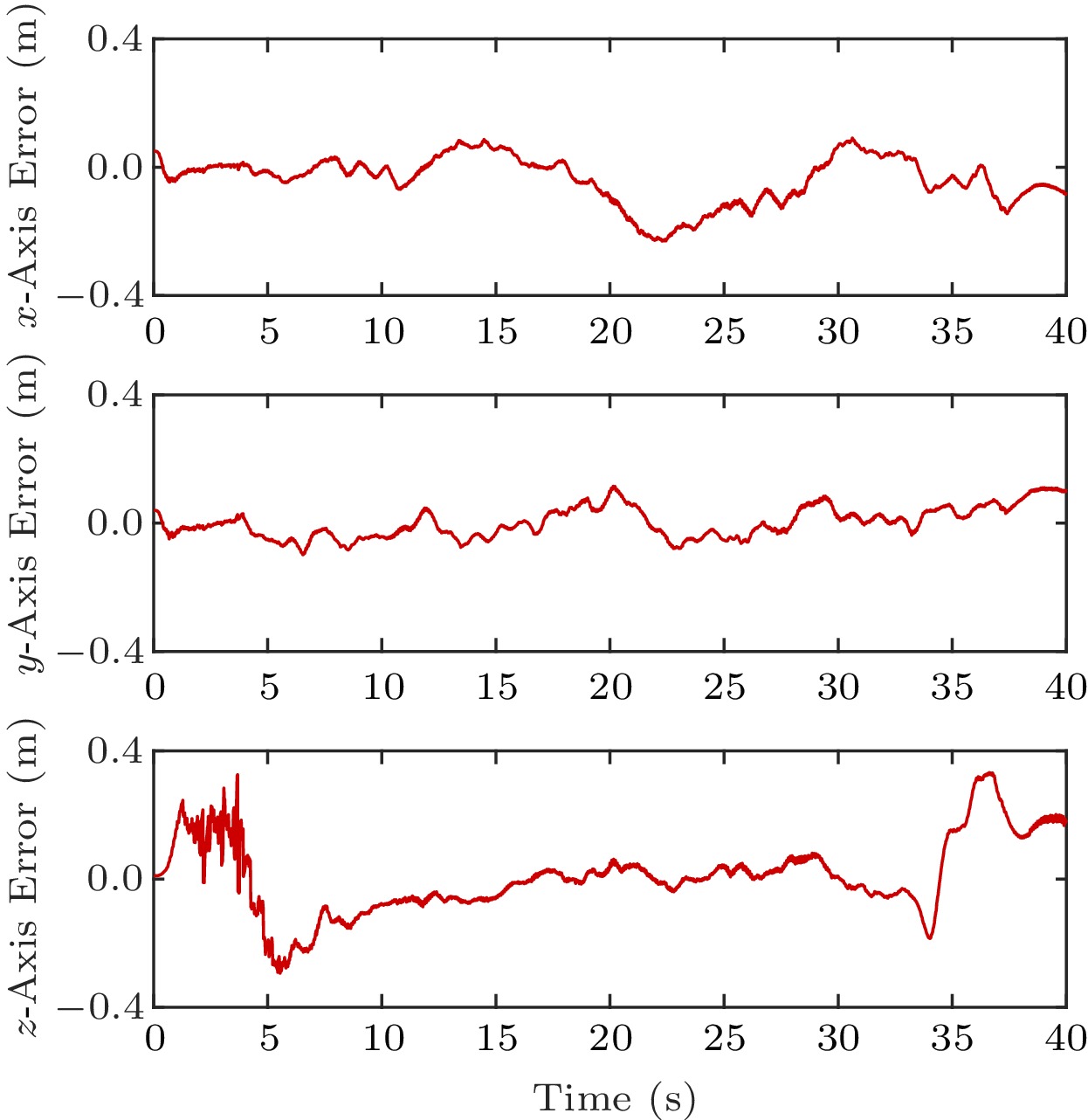
0.0225 m2, and the measurement loss rate is up to 32.5%, which are both higher than those in the underground garage. Compared with the underground garage, the performance of the ESKF localization algorithm is reduced by 14.5%.Fig.12 presents the trajectory of the UAV in the coal mine tunnel. The performances of all the algorithms have a certain degradation compared with the underground garage. Especially, due to the random jitter of UWB ranging and the IMU attitude bias, the localization performance sharply decreases when the UAV turns. Despite that, the proposed UO-EKF still shows satisfactory localization results. Fig.13 further describes the CDF of the localization errors. The maximum and average localization errors of ESKF are about 0.461 m and 0.253 m by calculation, respectively, while the corresponding errors of the UO-EKF are 0.284 m and 0.205 m, respectively. It is worth noting that the performance improvement in the coal mine is about 19.0%, which is obviously more remarkable than that in the underground garage. It confirms that the proposed UO-EKF with unreliable observations has stronger robustness and accuracy in hostile coal mine environments. Besides, it can be seen from Fig.14 that the maximum errors of three axes for UO-EKF are less than 0.4 m, and the average errors are only 0.21 m, 0.16 m, and 0.23 m, respectively.
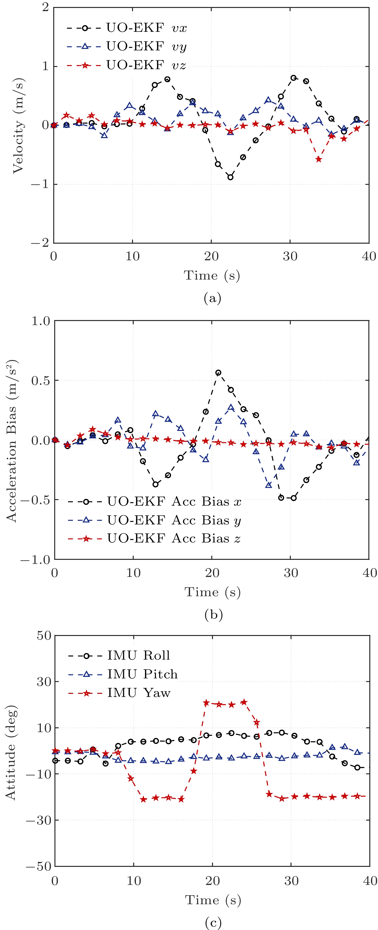
Although the true values of velocity and acceleration bias are unavailable in our system configuration, we argue that the estimated velocity and acceleration bias in Fig.15 are reasonable based on the accuracy of the above localization results. Specifically, we can see from Fig.15(a) that the speed of the UAV does not exceed 1 m/s, which accords with the maximum linear speed setup of the UAV. Furthermore, as can be seen from Fig.15(b), the acceleration bias estimation fluctuates around 0, and the maximum value is not larger than 0.5 m/s2, which validates there are no cumulative errors in the proposed localization scheme. In addition, since the external transformation between the IMU and the navigation coordinate system is required for localization, we additionally estimate the UAV attitudes shown in Fig.15(c). Eventually, results show that the yaw, roll, and pitch angles are also consistent with the UAV's physical flight attitude.
In the end, the RMSEs of these typical algorithms are given in Table 4. Although the UWB measurements are unreliable and lost seriously in the coal mine, our scheme can still achieve accurate and robust localization with RMSE 0.217 m. Furthermore, the accuracy is improved by 16.9\% compared with ESKF. Through the above experimental results, we can conclude that the proposed UO-EKF can satisfy the requirements of UAV localization in hostile coal mines.
7. Related Work
Multi-Sensor Fusion. The localization schemes based on multi-sensor fusion have attracted extensive research, especially the fusion of UWB and IMU. The localization performances between the fusion of IMU in the prediction step and in the update step are compared in [36], and the results show that the latter has better performance. In [26], IMU is utilized as the control input in the prediction step to estimate the acceleration bias, which reduces the localization delay and improves the accuracy. However, the linearization error introduced by EKF promotes the research of localization algorithms based on UKF[15], ESKF[14], and particle filter[21]. Moreover, a coupled UWB/INS localization framework is proposed in [37], and the minimum variance unbiased finite impulse response method is utilized to obtain accurate position and velocity estimation. It has better immunity to the error of prior knowledge of noise variance. In [38], a composite filtering is developed for UAV localization with the TDOA-based UWB, which can deal with measurement noise and dynamic uncertainty simultaneously. Although the linearization error is reduced, the issues of measurement error and loss in the complex environment, have not been well solved. To achieve accurate and robust localization performance in complex scenes, an elastically tightly coupled UWB visual-inertial indoor localization system (R-UVIS) is designed in [39]. Due to the dark, low illumination, and less texture environment in the hostile underground coal mine scenarios, the method of fusing visual sensors is not applicable.
NLOS Localization. Many algorithms are proposed for large UWB range measurement errors because of NLOS, like constraint optimization[40], H-infinity filter (HIF)[41], and cubature KF (CKF)[42]. In [29], a UWB NLOS mitigation for localization is proposed. It introduces the equality-constrained Taylor series robust least squares (ECTSRLS) technique to suppress residual NLOS range errors. In the harsh coal mine environments, the proposed ESKF-fusion[34] is only a linear fitting of UWB measurement, which cannot solve the problem of inaccurate UWB ranging. VBUKF[43] was proposed to reduce the interference of NLOS by smoothing with the consideration of time-variant measurement noise. Based on machine learning and deep learning, some ranging error identification and elimination algorithms are also proposed in [44, 45]. The algorithm is combined with EKF, and the accurate range difference is selected for calculation, which effectively reduces the NLOS measurement error. Nevertheless, the above methods usually deal with the UWB ranging measurement error independently and are not closely combined with the localization algorithm. This paper starts from the localization algorithm, and both inaccurate and lost UWB measurements are the focus and challenge of our work.
8. Conclusions
In this paper, we designed a novel UAV localization framework UO-EKF to handle the outliers and losses of ranging measurements in hostile underground environments. Based on the fusion of UWB and IMU, three localization algorithms, AEKF, CEKF, and AREKF, were proposed in the localization framework. AEKF is used to detect and correct outliers, which improves the accuracy of localization. In addition, CEKF and AREKF are used to compensate for the loss of range measurements, which further promotes the localization performance. Simulations and experiments showed that the proposed UO-EKF is feasible and can achieve better robustness and accuracy in hostile underground environments. In future work, we will further improve the localization algorithm to expand application areas.
-
Table 1 Parameters in Simulations
Parameter Value Gyroscope noise ( {^{\circ}/{\rm{s}}}) 0.2\times10^{-3} Acceleration noise ( {{\mu}{\rm{g}}}) 1.6\times10^{-2} Gyroscope random walk ({^{\circ}/ {\rm{h}}}) 8.0\times10^{-6} Acceleration random walk ({{\mu}{\rm{g}}}) 0.1\times10^{-2} UWB frequency (Hz) 5.0\times10^{1} IMU frequency (Hz) 1.0\times10^{2} Table 2 Parameters in Underground Garage Experiments
Parameter Value Gyroscope noise ( {^{\circ}/{\rm{s}}/{\rm{g}}}) 0.1000 Acceleration noise ({{\rm{g}}/{\sqrt{{\rm{Hz}}}}}) 0.0015 Gyroscope random walk ( {^{\circ}/{\rm{s}}}) 1.0000 Acceleration random walk (g) 0.0300 UWB frequency (Hz) 50.0000 IMU frequency (Hz) 100.0000 UWB variance ( {\rm{m}}^2) 0.0036 Table 3 Performance in Underground Garage
-
[1] Gaber T, El Jazouli Y, Eldesouky E, Ali A. Autonomous haulage systems in the mining industry: Cybersecurity, communication and safety issues and challenges. Electronics, 2021, 10(11): 1357. DOI: 10.3390/electronics10111357.
[2] Shahmoradi J, Talebi E, Roghanchi P, Hassanalian M. A comprehensive review of applications of drone technology in the mining industry. Drones, 2020, 4(3): 34. DOI: 10.3390/drones4030034.
[3] Li H, Savkin A V, Vucetic B. Autonomous area exploration and mapping in underground mine environments by unmanned aerial vehicles. Robotica, 2020, 38(3): 442–456. DOI: 10.1017/S0263574719000754.
[4] Turner R M, MacLaughlin M M, Iverson S R. Identifying and mapping potentially adverse discontinuities in underground excavations using thermal and multispectral UAV imagery. Engineering Geology, 2020, 266: 105470. DOI: 10.1016/j.enggeo.2019.105470.
[5] Yuan G, Wang Y, Zhao F, Wang T, Zhang L, Hao M, Yan S, Dang L, Peng B. Accuracy assessment and scale effect investigation of UAV thermography for underground coal fire surface temperature monitoring. International Journal of Applied Earth Observation and Geoinformation, 2021, 102: 102426. DOI: 10.1016/j.jag.2021.102426.
[6] Yao Z, Cheng W, Zhang W, Zhang T, Zhang H. The rise of UAV fleet technologies for emergency wireless communications in harsh environments. IEEE Network, 2022, 36(4): 28–37. DOI: 10.1109/MNET.001.2100691.
[7] Sun W, Xue M, Yu H, Tang H, Lin A. Augmentation of fingerprints for indoor WiFi localization based on Gaussian process regression. IEEE Trans. Vehicular Technology, 2018, 67(11): 10896–10905. DOI: 10.1109/TVT.2018.2870160.
[8] Jiang X, Chen Y, Liu J, Gu Y, Hu L. FSELM: Fusion semi-supervised extreme learning machine for indoor localization with Wi-Fi and Bluetooth fingerprints. Soft Computing, 2018, 22(11): 3621–3635. DOI: 10.1007/s00500-018-3171-4.
[9] Bahl P, Padmanabhan V N. RADAR: An in-building RF-based user location and tracking system. In Proc. the 19th Annual Joint Conference of the IEEE Computer and Communications Societies, Mar. 2000, pp.775–784. DOI: 10.1109/INFCOM.2000.832252.
[10] Luo R C, Hsiao T J. Dynamic wireless indoor localization incorporating with an autonomous mobile robot based on an adaptive signal model fingerprinting approach. IEEE Trans. Industrial Electronics, 2019, 66(3): 1940–1951. DOI: 10.1109/TIE.2018.2833021.
[11] Pecoraro G, Di Domenico S, Cianca E, De Sanctis M. CSI-based fingerprinting for indoor localization using LTE signals. EURASIP Journal on Advances in Signal Processing, 2018, 2018: Article No. 49. DOI: 10.1186/s13634-018-0563-7.
[12] Zhu X, Yi J, Cheng J, He L. Adapted error map based mobile robot UWB indoor positioning. IEEE Trans. Instrumentation and Measurement, 2020, 69(9): 6336–6350. DOI: 10.1109/TIM.2020.2967114.
[13] Corrales J A, Candelas F A, Torres F. Hybrid tracking of human operators using IMU/UWB data fusion by a Kalman filter. In Proc. the 3rd ACM/IEEE International Conference on Human Robot Interaction, Mar. 2008, pp.193–200. DOI: 10.1145/1349822.1349848.
[14] Wen K, Yu K, Li Y, Zhang S, Zhang W. A new quaternion Kalman filter based foot-mounted IMU and UWB tightly-coupled method for indoor pedestrian navigation. IEEE Trans. Vehicular Technology, 2020, 69(4): 4340–4352. DOI: 10.1109/TVT.2020.2974667.
[15] Feng D, Wang C, He C, Zhuang Y, Xia X G. Kalman-filter-based integration of IMU and UWB for high-accuracy indoor positioning and navigation. IEEE Internet of Things Journal, 2020, 7(4): 3133–3146. DOI: 10.1109/JIOT.2020.2965115.
[16] Xu Y, Ahn C K, Shmaliy Y S, Chen X, Li Y. Adaptive robust INS/UWB-integrated human tracking using UFIR filter bank. Measurement, 2018, 123: 1–7. DOI: 10.1016/j.measurement.2018.03.043.
[17] Yoon P K, Zihajehzadeh S, Kang B S, Park E J. Robust biomechanical model-based 3-D indoor localization and tracking method using UWB and IMU. IEEE Sensors Journal, 2017, 17(4): 1084–1096. DOI: 10.1109/JSEN.2016.2639530.
[18] Fang J, Gong X. Predictive iterated Kalman filter for INS/GPS integration and its application to SAR motion compensation. IEEE Trans. Instrumentation and Measurement, 2010, 59(4): 909–915. DOI: 10.1109/TIM.2009.2026614.
[19] Yin H, Xia W, Zhang Y, Shen L. UWB-based indoor high precision localization system with robust unscented Kalman filter. In Proc. the 2016 IEEE International Conference on Communication Systems, Dec. 2016. DOI: 10.1109/ICCS.2016.7833646.
[20] Li S, Xu B, Wang L, Razzaqi A A. Improved maximum correntropy cubature Kalman filter for cooperative localization. IEEE Sensors Journal, 2020, 20(22): 13585–13595. DOI: 10.1109/JSEN.2020.3006026.
[21] Raja G, Suresh S, Anbalagan S, Ganapathisubramaniyan A, Kumar N. PFIN: An efficient particle filter-based indoor navigation framework for UAVs. IEEE Trans. Vehicular Technology, 2021, 70(5): 4984–4992. DOI: 10.1109/TVT.2021.3072727.
[22] Lesage-Landry A, Taylor J A, Shames I. Second-order online nonconvex optimization. IEEE Trans. Automatic Control, 2021, 66(10): 4866–4872. DOI: 10.1109/TAC.2020.3040372.
[23] Sabatini A M. Variable-state-dimension Kalman-based filter for orientation determination using inertial and magnetic sensors. Sensors, 2012, 12(7): 8491–8506. DOI: 10.3390/s120708491.
[24] Strohmeier M, Walter T, Rothe J, Montenegro S. Ultra-wideband based pose estimation for small unmanned aerial vehicle. IEEE Access, 2018, 6: 57526–57535. DOI: 10.1109/ACCESS.2018.2873571.
[25] Fang X, Wang C, Nguyen T M, Xie L. Model-free approach for sensor network localization with noisy distance measurement. In Proc. the 15th International Conference on Control, Automation, Robotics and Vision, Nov. 2018, pp.1973–1978. DOI: 10.1109/ICARCV.2018.8581124.
[26] Li J, Bi Y, Li K, Wang K, Lin F, Chen B M. Accurate 3D localization for MAV swarms by UWB and IMU fusion. In Proc. the 14th IEEE International Conference on Control and Automation, Jun. 2018, pp.100–105. DOI: 10.1109/ICCA.2018.8444329.
[27] Zhang J H, Li P, Jin C C, Zhang W A, Liu S. A novel adaptive Kalman filtering approach to human motion tracking with magnetic-inertial sensors. IEEE Trans. Industrial Electronics, 2020, 67(10): 8659–8669. DOI: 10.1109/TIE.2019.2946557.
[28] Dardari D, Conti A, Ferner U, Giorgetti A, Win M Z. Ranging with ultrawide bandwidth signals in multipath environments. Proceedings of the IEEE, 2009, 97(2): 404–426. DOI: 10.1109/JPROC.2008.2008846.
[29] Yu K, Wen K, Li Y, Zhang S, Zhang K. A novel NLOS mitigation algorithm for UWB localization in harsh indoor environments. IEEE Trans. Vehicular Technology, 2019, 68(1): 686–699. DOI: 10.1109/TVT.2018.2883810.
[30] Cunha F, Youcef-Toumi K. Ultra-wideband radar for robust inspection drone in underground coal mines. In Proc. the 2018 IEEE International Conference on Robotics and Automation, May 2018, pp.86–92. DOI: 10.1109/ICRA.2018.8461191.
[31] Bai Y T, Wang X Y, Jin X B, Zhao Z Y, Zhang B H. A neuron-based Kalman filter with nonlinear autoregressive model. Sensors, 2020, 20(1): Article No. 299. DOI: 10.3390/s20010299.
[32] Khan N, Bacha S A, Khan S A, Afrasiab. Improvement of compensated closed-loop Kalman filtering using autoregressive moving average model. Measurement, 2019, 134: 266–279. DOI: 10.1016/j.measurement.2018.10.063.
[33] Khan N, Khattak M I, Khan M N, Khan F, Khan L U, Salam S A, Gu D. Implementation of linear prediction techniques in state estimation. In Proc. the 10th International Bhurban Conference on Applied Sciences & Technology, Jan. 2013, pp.77–83. DOI: 10.1109/IBCAST.2013.6512134.
[34] Li M G, Zhu H, You S Z, Tang C Q. UWB-based localization system aided with inertial sensor for underground coal mine applications. IEEE Sensors Journal, 2020, 20(12): 6652–6669. DOI: 10.1109/JSEN.2020.2976097.
[35] Chóliz J, Eguizábal M, Hernández-Solana Á, Valdovinos A. Comparison of algorithms for UWB indoor location and tracking systems. In Proc. the 73rd IEEE Vehicular Technology Conference, May 2011. DOI: 10.1109/VETECS.2011.5956174.
[36] Miraglia G, Maleki K N, Hook L R. Comparison of two sensor data fusion methods in a tightly coupled UWB/IMU 3-D localization system. In Proc. the 2017 International Conference on Engineering, Technology and Innovation, Jun. 2017, pp.611–618. DOI: 10.1109/ICE.2017.8279941.
[37] Zhao S, Huang B, Liu F. Localization of indoor mobile robot using minimum variance unbiased FIR filter. IEEE Trans. Automation Science and Engineering, 2018, 15(2): 410–419. DOI: 10.1109/TASE.2016.2599864.
[38] Jia J, Guo K, Li W, Yu X, Guo L. Composite filtering for UWB-based localization of quadrotor UAV with skewed measurements and uncertain dynamics. IEEE Trans. Instrumentation and Measurement, 2022, 71: 1002313. DOI: 10.1109/TIM.2022.3151934.
[39] Yang B, Li J, Zhang H. Resilient indoor localization system based on UWB and visual-inertial sensors for complex environments. IEEE Trans. Instrumentation and Measurement, 2021, 70: 8504014. DOI: 10.1109/TIM.2021.3101322.
[40] Venkatesh S, Buehrer R M. NLOS mitigation using linear programming in ultrawideband location-aware networks. IEEE Trans. Vehicular Technology, 2007, 56(5): 3182–3198. DOI: 10.1109/TVT.2007.900397.
[41] Zhang Z, Hu N, Guo Y, Yang X. The NLOS localization algorithm based on the linear regression model of hybrid filter. In Proc. the 2019 Chinese Control and Decision Conference, Jun. 2019, pp.2442–2445. DOI: 10.1109/CCDC.2019.8832987.
[42] Wang J, Zhang T, Xu X, Li Y. A variational Bayesian based strong tracking interpolatory cubature Kalman filter for maneuvering target tracking. IEEE Access, 2018, 6: 52544–52560. DOI: 10.1109/ACCESS.2018.2869020.
[43] Cao B, Wang S, Ge S, Liu W. Improving positioning accuracy of UWB in complicated underground NLOS scenario using calibration, VBUKF, and WCA. IEEE Trans. Instrumentation and Measurement, 2021, 70: 8501013. DOI: 10.1109/TIM.2020.3035579.
[44] Stahlke M, Kram S, Mutschler C, Mahr T. NLOS detection using UWB channel impulse responses and convolutional neural networks. In Proc. the 2020 International Conference on Localization and GNSS, Jun. 2020. DOI: 10.1109/ICL-GNSS49876.2020.9115498.
[45] Wang T, Hu K, Li Z, Lin K, Wang J, Shen Y. A semi-supervised learning approach for UWB ranging error mitigation. IEEE Wireless Communications Letters, 2021, 10(3): 688–691. DOI: 10.1109/LWC.2020.3046531.
-
其他相关附件
-
本文附件外链
https://rdcu.be/d6X8J -
DOCX格式
3020-Chinese-Information 点击下载(51KB) -
PDF格式
2024-6-12-3020-Highlights 点击下载(919KB)
-


 下载:
下载:
