PuzzleNet: 基于边界感知与特征匹配的无重叠三维点云拼接方法
PuzzleNet: Boundary-Aware Feature Matching for Non-Overlapping 3D Point Clouds Assembly
-
摘要:研究背景
三维形状拼接与装配是创建复杂三维场景的重要手段,也是计算机图形学研究的基本问题之一。基于无重叠点云的形状拼接是许多实际应用领域的基础,诸如三维模型设计、考古以及机器人等学科。当瓷器类物体被打碎成多块时,我们需要分别对这些碎片进行扫描,然后自动拼接成一个完整的三维数字化模型。然而如何将现有的部分重叠的三维形状拼接方法扩展到无重叠点云,仍然是一个开放性问题。
目的我们的研究目标是提出一种仅通过几何特征将多个完全无重叠的点云拼接为一个完整点云的方法。受拼图游戏的启发,点云之间的几何边界信息可以作为拼接两个无重叠点云的线索。
方法我们提出一种称为 PuzzleNet的人工神经网络模型,在该模型中,同时对拼接两个点云的空间变换矩阵和边界点进行学习。设计了一个基于注意力机制的点云特征编码器分别学习点云的全局形状特征和局部逐点特征,分别作为两个并行的解码器分支的输入,学习两个点云拼接的空间变换矩阵和边界点集合。与单任务网络相比,额外的边界点提取分支不仅可以作为微调变换矩阵的依据,进而得到更好的拼接结果,还可以用于设计迭代式贪心方法,通过点云之间边界点进行匹配将两个点云的拼接方法扩展成将多个点云拼接为一个完整形状的方法。
结果我们在真实城市场景的扫描数据集DublinCity和CAD合成数据集 ModelNet40上训练和测试了本文提出的PuzzleNet。实验证明该方法在解决任意几何形状和语义标签不一致的多部件3D 形状组装方面的有效性。与相关的先进形状匹配和三维点云配准方法相比,我们的方法具有更好的拼接效果。
结论我们通过引入名为PuzzleNet的深度神经网络,利用纯几何信息学习组装非重叠点云,进一步提升了3D形状装配的水平。PuzzleNet受拼图解决方案的启发,通过同时推断刚性变换和边界特征,学习准确的点云对齐,其中两个解码器被精心设计为在一个统一的网络中不受彼此影响。借助于边界特征的学习和匹配,多块组装可以通过迭代贪心算法实现。我们通过与最先进的方法在合成和实际扫描数据集上的比较,证明了我们方法的有效性和优势。
Abstract:We address the 3D shape assembly of multiple geometric pieces without overlaps, a scenario often encountered in 3D shape design, field archeology, and robotics. Existing methods depend on strong assumptions on the number of shape pieces and coherent geometry or semantics of shape pieces. Despite raising attention to 3D registration with complex or low overlapping patterns, few methods consider shape assembly with rare overlaps. To address this problem, we present a novel framework inspired by solving puzzles, named PuzzleNet, which conducts multi-task learning by leveraging both 3D alignment and boundary information. Specifically, we design an end-to-end neural network based on a point cloud transformer with two-way branches for estimating rigid transformation and predicting boundaries simultaneously. The framework is then naturally extended to reassemble multiple pieces into a full shape by using an iterative greedy approach based on the distance between each pair of candidate-matched pieces. To train and evaluate PuzzleNet, we construct two datasets, named DublinPuzzle and ModelPuzzle, based on a real-world urban scan dataset (DublinCity) and a synthetic CAD dataset (ModelNet40) respectively. Experiments demonstrate our effectiveness in solving 3D shape assembly for multiple pieces with arbitrary geometry and inconsistent semantics. Our method surpasses state-of-the-art algorithms by more than 10 times in rotation metrics and four times in translation metrics.
-
Keywords:
- shape assembly /
- 3D registration /
- geometric learning /
- boundary feature /
- point cloud
-
1. Introduction
Shape assembly to create 3D complex scenes is one of the most central problems in computer graphics. Assembling non-overlapping point clouds is fundamental to many practical applications, such as 3D design[1], field archaeology[2], visual art[3], and robotics. For example, when an object like porcelain is broken into multiple pieces, we need to scan the pieces and automatically assemble them to form a complete one. This is challenging in several aspects. First, the multiple pieces are usually highly or low overlapped, making it difficult to determine their alignment. Second, shape pieces may have arbitrary geometry and no consistent semantics, and thus reconstruction has to be purely based on the geometric cues. Third, the target shape is usually composed of multiple pieces, where the organization of different pieces is unknown.
Assembling multiple shape pieces consists of two key steps, i.e., pairwise part alignment and multiple parts assembly. Pairwise part alignment registers two pieces so that they can be fused together seamlessly. Multi-piece assembly finds the correct connectivity between individual pieces to make a plausible configuration. These two steps are intertwined and make the problem more challenging
1 .Previous researchers have made many attempts at shape assembly. A typical line of studies[4, 5] match two disassembled shape pieces by exploring implicit shape reconstruction or field guidance. However, these methods mainly focus on the assembly of two pieces and cannot handle multiple ones with complex connectivity. Recent studies[6-8] have dealt with shape assembly of multiple shape parts with consistent semantic labels. Therefore these methods suffer from generalization when encountering shape pieces with arbitrary geometry and without coherent semantics.
A key step for shape assembly is partial shape alignment. Despite extensive studies, most previous studies focus on 3D registration[9], which usually has a heavy reliance on high overlaps. Recently, there have been also an increasing number of literatures on low overlapping scenarios for more robust 3D registration[10, 11]. However, it is still an open problem about how to extend the scheme to 3D shape assembly, which usually assumes rare or even no overlaps.
To address the above challenges, we present a novel deep learning based framework, named PuzzleNet. Our basic idea is inspired by puzzle solving, where puzzles with similar boundary features tend to be assembled together and the alignment quality between the boundaries of two pieces hints if the two pieces are well aligned. In shape assembly, disassembled point clouds are usually aligned by matching the boundaries and the corresponding pieces' extensions. Therefore boundary features are informative about the final alignment. As for the assembly of multiple pieces, we can check whether two pieces are aligned by comparing the corresponding boundary distances.
Our PuzzleNet comprises three steps, i.e., 3D transformation estimation, boundary point classification, and multi-piece assembly. The first two steps are learned with an end-to-end multi-task neural network, while the last step takes a greedy strategy to find the best-aligned pieces one by one until the final assembled shape is attained. For transformation estimation and boundary prediction, PuzzleNet combines an attention mechanism and a point-based learning module to focus on connecting boundaries implicitly. In particular, we employ a point-transformer-like network to predict the proper transformation matrix to align two point clouds.
Our contributions can be summarized as follows.
• We propose a novel framework for learning to assemble non-overlapping point clouds with arbitrary geometry and without prior semantic knowledge, as shown in Fig.1.
![]() Figure 1. PuzzleNet designed to automatically assemble complete shapes from multiple pieces. Given (a) four geometric pieces, (b) PuzzleNet learns pairwise shape alignment by predicting the transformation and the boundary information. (c) Then we achieve a full 3D shape by iteratively computing a global multi-piece assembly based on the distance between the boundaries of each pair.
Figure 1. PuzzleNet designed to automatically assemble complete shapes from multiple pieces. Given (a) four geometric pieces, (b) PuzzleNet learns pairwise shape alignment by predicting the transformation and the boundary information. (c) Then we achieve a full 3D shape by iteratively computing a global multi-piece assembly based on the distance between the boundaries of each pair.• We present a multi-task neural network, named PuzzleNet, for inferring rigid transformation and boundary features simultaneously. We show that the boundary-aware design can be used to iteratively reassemble multiple pieces into a full shape.
• We construct two datasets, named DublinPuzzle and ModelPuzzle, for studying the problem of multi-piece assembly by using the 3D data from DublinCity[12] and ModelNet40[13] respectively.
The rest of this paper is organized as follows. Section 2 describes the related work. Section 3 and Section 4 present the overview and technical details of our approach, respectively. After introducing the datasets we utilize in Section 5, we show the experimental results in Section 6. Finally, conclusions and future work are presented in Section 7.
2. Related Work
2.1 3D Shape Assembly
Over the past decades, shape assembly has been widely studied in computer graphics and computer vision communities. Many algorithms have been proposed to address part assembly that aims at assembling component parts for model creation. Huang et al.[5] introduced a field-guided registration algorithm by aligning two input parts in a feature-conforming manner. However, their method is only applicable to registering two parts and the open boundaries should be well-defined. The majority of subsequent methods apply deep neural networks to facilitate assembly-based modeling by leveraging part segmentation[7, 14-17] or formulating part assembly as a graph learning problem[6, 18]. Therefore, the above methods usually rely on a part database (e.g., PartNet[19]) or assume prior part semantics.
Without the assistance of known semantic labels, researchers propose to reassemble the original shape from a set of fragments. The typical pipeline of geometric guided methods[2, 20, 21] is to construct different handcraft features of contacting regions, and then increasingly reassemble shapes from many candidate matches. For example, Huang et al.[2] presented a system for fragmented solid reassembly, but they required an explicit segmentation step to construct patch-based fracture surface features. Zhang et al.[21] reassembled broken pieces by using template guidance, i.e., composing fragmented pieces based on their best match to a complete model. Neural shape mating (NSM)[4] is the most related to our method, which focuses on learning the alignment of two non-overlapping point clouds from geometric information rather than semantics. NSM develops a transformer-based rigid pose regressor to learn to approximate the spatial transformation, and then adopts an adversarial learning scheme that learns shape priors for evaluating the plausibility of the predicted shape mating configurations. However, this approach is designed for only aligning two object parts as they cannot conduct contact-region matching. Instead, our PuzzleNet explicitly learns boundary features and assembles multiple pieces by exploiting the similarities in the local boundary geometry of adjacent pieces.
2.2 Point Cloud Registration
The task of shape assembly is also intimately related to 3D shape registration. Classical 3D registration methods can be divided into global registration and local registration. The former computes a coarse alignment of two shapes, while the latter aims at further improving the accuracy of the initial estimate. Global registration methods work through the mechanism of first searching correspondence based on geometric features (e.g., point-based[22-26] or primitive-based[27, 28] descriptors), and then estimating the transformation by using an RANSAC-like algorithm[29]. For local registration, ICP[30] and its variants[31-33] are the representatives that iteratively search closet points and update transformation by solving a least square problem.
Thanks to the advances in point-based 3D deep learning[34-37], deep point cloud registration has also drawn a lot of attention recently. Such methods either estimate an accurate correspondence search by robustly feature learning[38-41], or directly learn the final transformation matrix by proposing end-to-end neural networks[42-44]. Although achieving encouraging results for dense point clouds, they have problems when the input has a small overlapping area. Thus, registration with low overlap has become the focus of research. PREDATOR[10] first introduces an overlap attention block that concentrates on the points in the overlapping region and predicts the saliency of overlap points. GeoTransformer[11] proposes a geometric transformer for accurate super-point mapping, making it robust in low-overlapped cases. NgeNet[45] utilizes a geometric guided encoding module and a multi-scale architecture to learn point-wise features, and then applies a learning-free voting strategy for filtering wrong feature mappings. PCAM[46] learns the matching regions by a point-wise product of cross-attention matrices mixing both low-level and high-level features. OMNet[47] learns masks to reject non-overlapping geometric features. However, the above methods still heavily rely on overlapping regions, and thus they cannot handle non-overlap examples as in our work.
3. Overview of Our Method
3.1 Problem Formulation
Given a set of point clouds without overlaps, we aim to assemble them piece by piece to form an integrated shape. This can be decomposed into two subtasks of: 1) assembling two pieces with an optimal rigid transformation; 2) finding pair-wise pieces close to each other able to be assembled. As boundaries between two pieces usually give a clue about assemblable pieces, we convert the second sub-task as boundary prediction and matching. To make it brief, we take two point clouds {\boldsymbol{P}} \in {\mathbb{R}^{N\times3}} and {\boldsymbol{Q}} \in {\mathbb{R}^{N\times3}} as inputs to explain the problem.
For the first goal, we aim to predict a rigid transformation {\boldsymbol{T}}=[{\boldsymbol{R}}, {\boldsymbol{t}};{\bf{0}},{\bf{1}}] with 6 DoF (degree of freedom), where R is a rotation matrix and {\boldsymbol{t}} \in \mathbb{R}^3 is a translation vector. The rigid transformation transforms the point cloud Q to {{\boldsymbol{\bar{Q}}}} that has the closest distance to the ground truth {\boldsymbol{\hat{Q}}} . In this way, the objective function (1) in the following is minimized:
\mathop{\arg\min}_{{\boldsymbol{R}}\in {SO}\left(3\right) , {\boldsymbol{t}}\in \mathbb{R}^3} d_{\rm pc}\left({\boldsymbol{\hat{Q}}}, {\boldsymbol{R}}{\boldsymbol{Q}} + {\boldsymbol{t}} \right), (1) where d_{\rm pc}(\cdot, \cdot) is a distance magnanimity of two point clouds.
The second goal is to predict the boundary between the two point clouds, i.e., classifying each point in P (or {\boldsymbol{\hat{Q}}} ) as interior points or boundary points. In this way, the boundary prediction task can be formulated as (2):
\begin{align} \mathop{\arg\min}_{{\boldsymbol{B_{P}}} \subset {\boldsymbol{P}},\ {\boldsymbol{B_{Q}}} \subset {\boldsymbol{Q}}} d_{\rm pc}\left( {\boldsymbol{B_{P}}},{\boldsymbol{\bar{Q}}} \right) + d_{\rm pc}\left( {\boldsymbol{P}}, {\boldsymbol{R}}{\boldsymbol{B_{Q}}} + {\boldsymbol{t}} \right), \end{align} (2) where {\boldsymbol{B_{P}}} \in \mathbb{R}^{N^{B} \times 3} and {\boldsymbol{B_{Q}}} \in \mathbb{R}^{N^{B} \times 3} are the boundary points extracted from the point clouds P and {\boldsymbol{Q}} , respectively. Last but not least, the possibility that two pieces are matched can be easily determined by the distances between transformed boundary points.
3.2 Our Approach
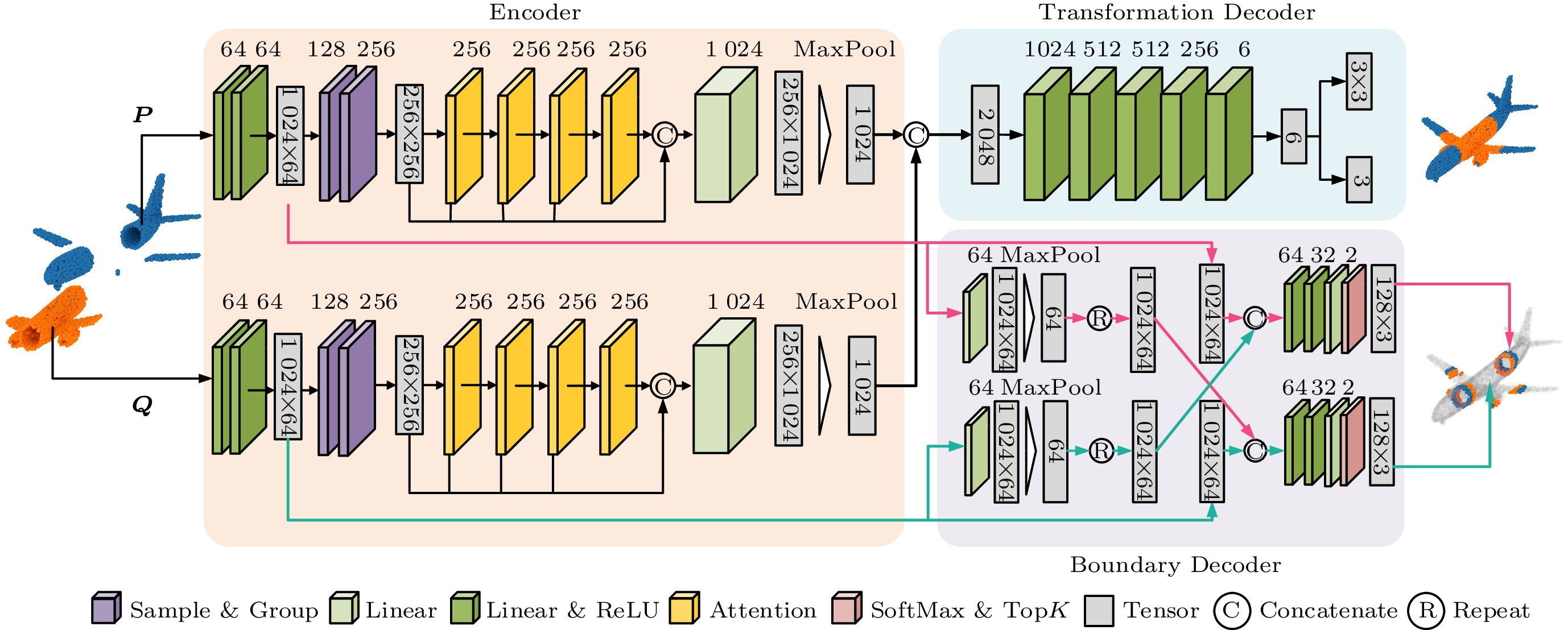
To tackle the above problem, we present a novel multi-task neural network that is composed of three main modules: one transformer-based point cloud encoder, and two decoder branches that infer transformation and boundary points, respectively.
Our pipeline is visualized in Fig.2. Given the input point clouds, we first extract latent geometry features from each point cloud by applying a transformer-based encoder (see Subsection 4.1). Specifically, the encoder outputs a global feature for pose estimation and a local feature for boundary prediction. Next, different decoders are used in two separate branches to decode the features for particular sub-tasks, which will be described in Subsection 4.2 and Subsection 4.3. For the pose estimation, the global features of the input point clouds are concatenated and passed to a transformation decoding module, which consists of a couple of fully-connected layers. This module directly learns a transformation matrix supervised by the ground-truth pose. For the boundary prediction, we consider using the local feature to recognize the explicit boundary points.
![]() Figure 2. Network architecture of our proposed PuzzleNet. We apply a transformer-based encoder to extract both global and local geometric features, which are then passed to two decoders to estimate a rigid transformation and predict the boundary respectively. The number of output channels is shown above the corresponding modules.
Figure 2. Network architecture of our proposed PuzzleNet. We apply a transformer-based encoder to extract both global and local geometric features, which are then passed to two decoders to estimate a rigid transformation and predict the boundary respectively. The number of output channels is shown above the corresponding modules.At last, we utilize an iterative greedy approach to assemble more than two pieces into a complete shape (Subsection 4.4). Given multiple pieces, we conduct pairwise matching by using our PuzzleNet to predict the transformation and boundary points between each pair. Then we select the best matching according to the distance between the boundary points, and the corresponding two point clouds are registered together as a new piece. This pairwise matching operation is repeated until all of the pieces are reassembled.
4. Details of Our Method
4.1 Point Cloud Encoder
Since our method focuses on learning alignment from geometric information rather than from semantic information, we compute geometric features for the input points by applying a point cloud encoder. Inspired by Point Cloud Transformer (PCT)[36], our encoder is built upon a transformer mechanism, which mainly consists of four components: feature mapping, sampling and grouping, attention-based feature augmentation, and feature aggregation. The detailed network architecture of this module is illustrated in Fig.2.
As mentioned above, the goal of the point cloud encoder is to extract the local contextual feature {\cal{F}}^{\rm l} and the global contextual feature {\cal{F}}^{\rm g} which is used in the following two-branch decoders. To this end, we take both point clouds P and Q as input for two encoders respectively in each epoch. The input points are uniformly downsampled with N = 1\;024 by employing a farthest point sampling (FPS) strategy. Then two fully-connected layers with batch-norm and ReLU activation functions are utilized as feature mapping, and the points' coordinates are mapped to a high-dimensional space as embedding features {\cal{F}}^{\rm l} \in \mathbb{R}^{N \times 64} . Different from the local feature (named as the point feature in PCT) extracted from the vanilla PCT, our local feature is extracted before the sampling modules with the purpose of avoiding messing up the back-propagation in our later multi-decoder network.
Then, two sampling and grouping (SG) modules are employed. In the first SG module, we downsample our local features further by half to obtain {\boldsymbol{P}}^\prime (or {\boldsymbol{Q}}^\prime ) containing N^\prime=512 points. Then for each sampled point {{\boldsymbol p}}^\prime_i , we consider its K nearest points {{\boldsymbol p}}^\prime_j , where K=32 in our network, and concatenate the point coordinates and the local features {\cal{F}}^{\rm l}_{j} to compute a new per-point feature {\cal{F}}^{\rm SG}_{i} \in \mathbb{R}^{K \times (64+3)} . Therefore, the point cloud {\boldsymbol{P}}^\prime (or {\boldsymbol{Q}}^\prime ) can be represented as a tensor {\cal{F}}^{\rm SG} with the shape of \mathbb{R}^{N^\prime \times K \times (64+3)} . Next, the concatenated feature {\cal{F}}^{\rm SG} is passed to two fully-connected layers with batch-norm and ReLU layers to remap the aggregated feature's dimension into \mathbb{R}^{N^\prime \times K \times 128} . The newly-created axis is then squeezed by max-pooling to gain the grouped feature with a shape of \mathbb{R}^{N^\prime \times 128} . In the second SG module, the above feature grouping process is performed again and we obtain a new feature {\cal{F}}^{\rm SG} \in \mathbb{R}^{\textstyle\frac{N^\prime}{2} \times 256}.
After SG modules, the above grouped feature {\cal{F}}^{\rm SG} is forward propagated by four offset-attention blocks to obtain four attention features \{{\cal{F}}^{\rm Att.}_i\}_{i=1}^4 . Then {\cal{F}}^{\rm SG} and the four attention features are concatenated in the feature channel and followed by a linear layer to align the length equal to input length N=1\;024 . Finally, the concatenated feature is fed into a max-pooling layer on the point-wise channel to obtain the global feature {\cal{F}}^{\rm g} \in \mathbb{R}^{1\;024}.
4.2 Transformation Estimation
The transformation estimation module is a core component of the proposed framework, which aims to infer the rigid pose T (i.e., {\boldsymbol{R}} and {\boldsymbol{t}} ) that aligns the point cloud {\boldsymbol{Q}} as close as the ground-truth {\boldsymbol{\hat{Q}}} . Different from traditional registration methods that rely on overlap points, our input point clouds are exactly disjointed without overlap regions, making it hard to align two point clouds by constructing valid point-wise feature correspondences from only the contacting boundaries. Instinctively, we take full advantage of the extracted global features of the pieces and formulate the pose estimation as a regression problem:
{{\boldsymbol S}} = {\cal{D}}_{ {T}}({\cal{F}}_{\boldsymbol P}^{\rm g}, {\cal{F}}_{\boldsymbol Q}^{\rm g}), where {\cal{D}}_{{\rm T}}(\cdot) is a transformation decoder, {\boldsymbol{S}} \in \mathfrak{se}\left(3\right) represents the transformation tensor predicted by our network, and {\cal{F}}_{\boldsymbol P}^{\rm g} and {\cal{F}}_{\boldsymbol Q}^{\rm g} are the global features of input point clouds P and {\boldsymbol{Q}} , respectively.
Specifically, we concatenate the two global features as {\cal{F}}^{\rm cross} to capture cross-piece information. By feeding {\cal{F}}^{\rm cross} into the decoder, two fully-connected layers with batch-norm and ReLU layers are employed to predict a tensor {\boldsymbol{S}} \in \mathfrak{se} \left(3\right) with a length of 6 representing the transformation T. The tensor {\boldsymbol{S}} is then converted to the rotation matrix {\boldsymbol{R}} and translation vector {\boldsymbol{t}} . The detailed parameters of this module can be referred to in Fig.2.
Training Loss. The pose estimation network is trained in a supervised fashion by an efficient joint loss function containing three components: mean squared error (MSE) loss, Chamfer Distance (CD) loss, and Earth Mover's Distance (EMD) loss:
\begin{align} \begin{split} L_{\rm pose} = L_{\rm MSE} + L_{\rm CD} + L_{\rm EMD}\,\text{.} \nonumber \end{split} \end{align} The MSE loss is used to evaluate the precision of the predicted transformation:
\begin{align} L_{\rm MSE} = MSE\left( {\boldsymbol{T}} \cdot {\boldsymbol{\bar{T}^{-1}}}, {\boldsymbol{I}} \right) \nonumber \end{align}, where {\boldsymbol{\bar{T}}}=[{\boldsymbol{\bar{R}}}, {\boldsymbol{\bar{t}}}; {\bf{0}}, {\bf{1}}] is the ground-truth transformation. If the pose is learned correctly, the matrix production of predicted transformation T and ground-truth {\boldsymbol{\bar{T}}} should be equal to the identity matrix I.
The second term L_{\rm CD} is the chamfer distance loss, which is a regular metric to evaluate the distance between two point clouds:
\begin{align}d_{\rm CD} ({\boldsymbol S_1}, {\boldsymbol S_2}) = \sum_{x\in {\boldsymbol S_1}}{\min_{y\in {\boldsymbol S_2}}{\lVert x-y \rVert}^2_2} + \sum_{y\in \boldsymbol S_2}{\min_{x\in {\boldsymbol S_1}}{\lVert x-y\rVert}^2_2}\end{align}, where {\boldsymbol S_1} and {\boldsymbol S_2} are two point sets. We use the Chamfer distance as a constraint between the ground-truth {\boldsymbol{\hat{Q}}} and the prediction {\boldsymbol{\bar{Q}}} as
\begin{align} L_{\rm CD} = d_{\rm CD}({\boldsymbol{\hat{Q}}}, {\boldsymbol{\bar{Q}}}),\nonumber \end{align} to find the transformation that converts the input {\boldsymbol{Q}} to the ground truth one.
The Earth Mover's Distance loss L_{\rm EMD} is another loss function that is commonly used for point cloud registration. The EMD loss is based on finding the one-to-one correspondence between the two point sets so that the sum of distances between corresponding points is minimal:
\begin{align} d_{\rm EMD}({\boldsymbol S_1}, {\boldsymbol S_2}) = \min_{\phi:{\boldsymbol S_1}\to {\boldsymbol S_2}}{\sum_{x \in {{\boldsymbol S_1}}} {\lVert x - \phi \left(x\right)\rVert}_2} \nonumber \end{align}, where \phi is a bijection. Our L_{\rm EMD} is then calculated by
\begin{align} L_{\rm EMD} = d_{\rm EMD} ({\boldsymbol{\hat{Q}}}, {\boldsymbol{\bar{Q}}}) \nonumber \end{align}. We train the pose estimation network with the loss function L_{\rm pose} to optimize (1), aiming to minimize the distance between point clouds {\boldsymbol{\hat{Q}}} and {\boldsymbol{\bar{Q}}} , as well as the distance between transformation matrices T and {\boldsymbol{\bar{T}}} .
4.3 Boundary Prediction
The boundary prediction module aims to extract the boundary points from each input point cloud. Note that we focus on the geometric alignment where we do not have particular semantic labels as in previous semantic segmentation methods[6], and there is no clear criterion for deciding which points should be the boundary points. To supervise the boundary prediction branch of our neural network, we regard the closest N^{B} points to the input point clouds as ground-truth boundary parts. We set N^{B}=128 by default in all of our experiments. Moreover, boundary prediction should not influence the back-propagation of transformation estimation encoding. To avoid messing up these two different functions in the encoding stage, the decoder for boundary predicting takes only two local features {\cal{F}}_{\boldsymbol P}^{\rm l} and {\cal{F}}_{\boldsymbol Q}^{\rm l} as inputs rather than the global context. We define the boundary prediction module by the following formulation:
\begin{aligned}[b] &{\boldsymbol{B_P}} = {\cal{D}}_{{\boldsymbol{B}}}^{\rm P} ( {\cal{F}}^{\rm l}_{\boldsymbol P}, {\cal{F}}^{\rm l}_{\boldsymbol Q} ), \\ & {\boldsymbol{B_Q}}= {\cal{D}}_{{\boldsymbol{B}}}^{\boldsymbol Q} ( {\cal{F}}^{\rm l}_{\boldsymbol Q}, {\cal{F}}^{\rm l}_{\boldsymbol P} ), \end{aligned} where {\cal{D}}_{{\boldsymbol{B}}}^P and {\cal{D}}_{{\boldsymbol{B}}}^Q are the decoders for predicting the boundary points.
To efficiently learn the local boundary information, both decoders must have receptive fields covering each other. Without loss of generality, we take the boundary prediction of point cloud P as an example to illustrate the prediction process, as indicated in Fig.2. Our network takes the low-level local features {\cal{F}}_{\boldsymbol P}^{\rm l} and {\cal{F}}_{\boldsymbol Q}^{\rm l} as inputs. Feature {\cal{F}}_{\boldsymbol Q}^{\rm l} with a shape of \mathbb{R}^{N \times 64} is first remapped into a feature with the same shape by a fully-connected layer. The point channel of the new feature is zeroed by a max-pooling operation and then repeated to form a high-level feature {\cal{F}}_{\boldsymbol Q}^{\rm h} \in \mathbb{R}^{N \times 64} that depicts the shape of {\boldsymbol{Q}} . By concatenating the low-level feature {\cal{F}}_{\boldsymbol P}^{\rm l} of P and the high-level feature {\cal{F}}_{\boldsymbol Q}^{\rm h} of {\boldsymbol{Q}} in the feature channel, we obtain a cross-geometry feature with a shape of \mathbb{R}^{N \times 128} . Next, linear layers with ReLU are employed to transform the cross-geometry feature into point-wise classification results {\cal{F}}_{\boldsymbol P}^{\boldsymbol B} \in \mathbb{R}^{N \times 2} , which infer the probabilities of a point belonging to the boundary or interior regions, respectively. Finally, we use a softmax function to obtain a one-dimensional probability score vector, and then we select the first N^{B} points with the highest probabilities as boundary points {\boldsymbol{B_P}} . The same operations are conducted on point cloud {\boldsymbol{Q}} to obtain {\boldsymbol{B_Q}} .
To supervise the training of the boundary prediction network, we leverage the cross-entropy loss and the Chamfer distance loss. We first use a cross-entropy (CE) to measure the loss between the predicted point-wise classification and the ground truth label:
\begin{align} L_{\rm CE} = CE ({\boldsymbol{B_P}}, {\boldsymbol{\hat{B_P}}})+ CE ({\boldsymbol{\hat{B_Q}}}, {\boldsymbol{B_Q}} \cdot {\boldsymbol{R}} + {\boldsymbol{t}}) \nonumber \end{align}, where {\boldsymbol{\hat{B_P}}} and {\boldsymbol{\hat{B_Q}}} are the ground-truth boundary points. the Chamfer loss is used to restrict the distance of predicted boundary points from the ground truth:
\begin{align} L_{\rm CD}^{\prime} = d_{\rm CD} ( {\boldsymbol{\hat{B_Q}}}, {\boldsymbol{B_Q}} \cdot {\boldsymbol{R}} + {\boldsymbol{t}}). \nonumber \end{align} The summation of L_{\rm CE} and L_{\rm CD}^{\prime} is minimized to optimize (2).
4.4 Multi-Piece Assembly Algorithm
Thanks to the proposed multi-task neural network, we are able to not only conduct reasonable pairwise alignment but also predict the open boundaries. This allows us to easily generalize the pairwise matching to multi-piece assembly by evaluating the performance of assembly through the distance between boundary points, which cannot be achieved by previous learning-based assembly approaches[4].
Given n unaligned and roughly cut pieces of point clouds from a 3D shape, we first perform the pairwise matching among all the pieces. Then, we construct an undirected complete graph {\cal{G}}=\{V,E\} , whose nodes V are the collection of input pieces, and edges E represent the matching relationships between the nodes. Initially, between each pair of nodes we build an edge as a candidate match by pairwise matching, and let Dis(E_i) denote the weight of such an edge and {\boldsymbol{T}}(E_i) be its estimated transformation. The weight Dis(E_i) is computed as the Chamfer distance of the predicted boundary points.
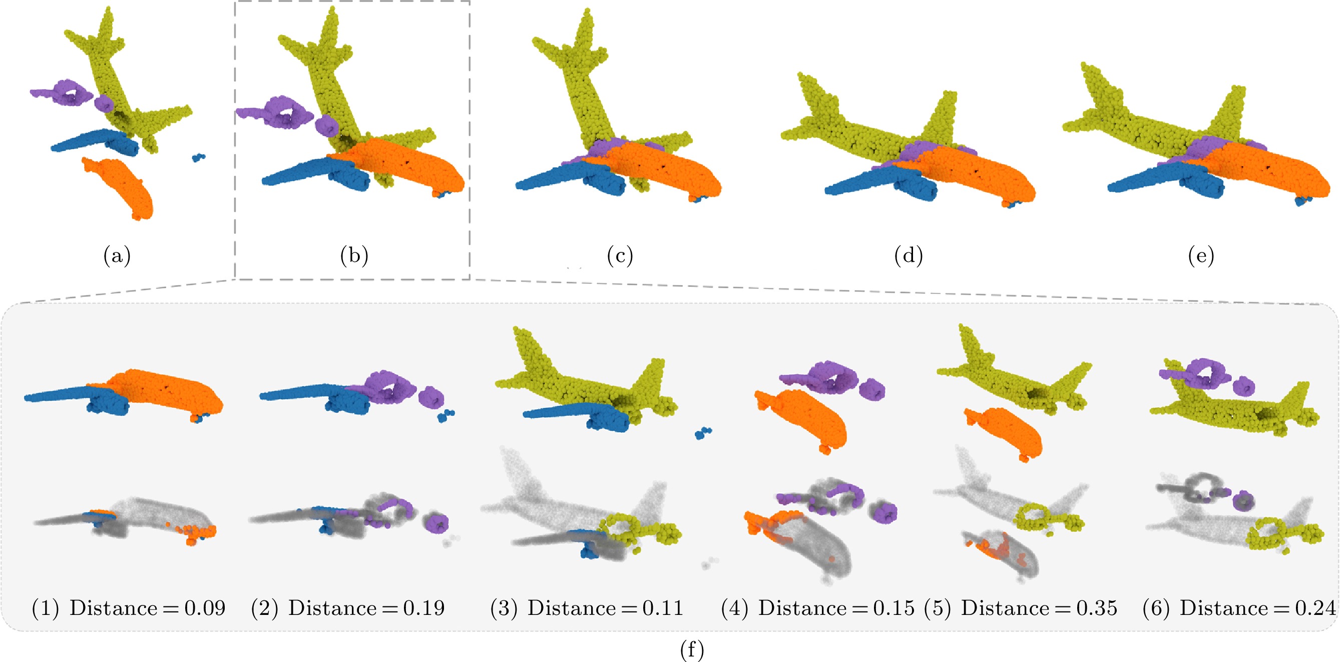
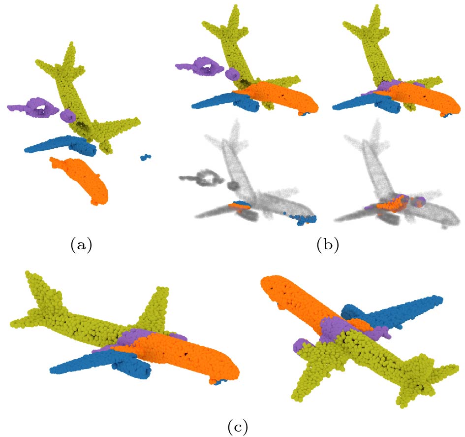
Based on the assumption that incorrect matches lead to large transformation errors, we propose a greedy approach to iteratively compute a multi-piece matching. At each iteration, we first select the best pairwise matching that has the least weighted edge E_i . We merge the two nodes into a new one by registering the corresponding point clouds together based on the predicted {\boldsymbol{T}}(E_i) . Then the point cloud of the new node is re-sampled into N=1\;024 points, and the graph {\cal{G}} is updated by pairwise matching between the new node and the other nodes. The above procedure is repeated until there only remains one node in the graph, i.e., all of the pieces have been reassembled into a complete shape. The numerical algorithm for multi-piece assembly is given in Algorithm 1, and Fig.3 visually illustrates the reassembling process with a 4-piece example.
![]() Figure 3. Illustration of our multi-piece assembly process. (a) Input: four pieces of point clouds. (b) Assembly result after the first iteration (iteration 1). (c) Assembly result after the second iteration (iteration 2). (d) Final assembly result after the third iteration (output). (e) Ground-truth assembly. (f) Detailed process of iteration 1. PuzzleNet is first applied to predict pairwise rigid pose and boundary points. Then we select the best alignment with the minimum distance between the boundary points. The selected two pieces are merged together and involved in later iterations.
Figure 3. Illustration of our multi-piece assembly process. (a) Input: four pieces of point clouds. (b) Assembly result after the first iteration (iteration 1). (c) Assembly result after the second iteration (iteration 2). (d) Final assembly result after the third iteration (output). (e) Ground-truth assembly. (f) Detailed process of iteration 1. PuzzleNet is first applied to predict pairwise rigid pose and boundary points. Then we select the best alignment with the minimum distance between the boundary points. The selected two pieces are merged together and involved in later iterations.5. Point Cloud Assembly Datasets
To train our PuzzleNet and demonstrate its efficacy, we utilize two kinds of datasets to construct two different datasets for the purpose of point cloud assembly, including a real-world scanned dataset and a synthetic CAD dataset.
Algorithm 1. Multi-Pieces Assembly Input: n pieces of unassembled point clouds S_P = \{P_{1}, P_{2},\ \dots,\ P_{n} \} Output: point cloud S_P^\prime representing the reassembled complete shape 1: n_{S} \gets 0 2: for P_i \in S_P do 3: S_i \gets MAKE-SET(P_i) //make a set 4: n_S \gets n_{S} + 1 5: end for 6: S_P \gets \{S_1, S_2, \dots, S_i, \dots, S_n\} 7: while n_{S} > 1 do 8: D_i^j \gets \{ \} 9: for S_i \gets \{S_1, \dots, S_{n-1} \} do 10: for S_j \gets \{S_{i+1}, \dots, S_{n} \} do 11: {\boldsymbol{T}}_i^j, d_i^j \gets PuzzleNET(FPS(S_i), FPS(S_j)) 12: D_i^j.add(d_i^j) 13: end for 14: end for 15: S_i, S_j \gets {\rm min}(\{D_i^j\}) 16: S_P.pop(S_i); S_P.pop(S_j) 17: S_P.add(UNION(S_i, S_j \cdot {\boldsymbol{T}}_i^j)) 18: n_S \gets n_S - 1 19: end while 20: S_P^\prime \gets\;S_P.pop(S_1) return S_P^\prime 5.1 DublinPuzzle Dataset
We first construct a real-world assembly dataset, named DublinPuzzle, by using the public DublinCity dataset[13], which contains airborne LiDAR point clouds with hierarchical labels for evaluating point cloud segmentation or classification algorithms. The objects of the city are classified into four categories: building, ground, vegetation, and undefined. Among them, building is the most complicated category with diverse types of historic and modern urban elements, such as offices, shops, libraries, and residential houses. Specifically, facade and roof are separated and attached with different labels manually as two disjoint parts of the buildings. This characteristic makes the dataset suitable for testing our PuzzleNet.
To prepare the DublinPuzzle, we manually extract all the buildings and then segment 3D building instances based on their semantic labels. Each building is assembled by two parts which represent facade and roof, respectively. After filtering the outliers, there remain about 600 buildings, which are randomly split into training (400), validation (100) and test (100) sets. All of the point clouds are downsampled by FPS with N=1\;024 points and normalized into a zero-centered unit sphere {[0,1]}^{3} .
Without the loss of generality, point clouds with label facade are regarded as P, while point clouds with label roof are treated as \boldsymbol Q . Then during training, each point cloud \boldsymbol Q is rotated and translated on the fly with a random transformation matrix \mathfrak{se}\left(3\right) . The rotation and the translation are initialized to range [0, 60^{\circ}] and [0, 1.0] following [48]. Note that although we have the semantic labels of each part, in our neural network we do not require semantic information and only focus on geometric alignment.
5.2 ModelPuzzle Dataset
We also evaluate our method on CAD models by building the ModelPuzzle dataset based on the public ModelNet40[12], from which we choose two categories of objects: 726 airplanes, and 608 beds. Our ModelPuzzle contains two parts. For the pairwise assembling task, we first build a dataset in two-piece mode, named as ModelPuzzle-P, which is treated as the first part of our ModelPuzzle dataset. We sample a dense point cloud from the original CAD models, and normalize the sampled points into a unit sphere. To cut each point cloud, we use different 3D primitives that are randomly placed in a unit sphere to cut a point cloud into two pieces. We define four different cutting types, each of which is represented by a specific primitive, including plane, sphere, cylinder and cone. After cutting, we uniformly sample each piece and conduct a random transformation as described in the DublinPuzzle dataset. Finally, we select 100 models as a test set for each category, and the remaining models are used as the training and validation sets with the rate of 9 : 1.
In the multi-piece mode, as a 3D shape may be cut into much smaller pieces revealing less global geometric features, we should train our network by extending the two-piece dataset to the multi-piece one. We adopt a coarse-to-fine cutting strategy. We call this dataset in the multi-piece mode as ModelPuzzle-M. As shown in Fig.4, we consider four basic cutting cases that can represent the most pairwise matching relationships among multi-piece data. 1) The most common case is that the whole shape is split into two pieces. 2) The whole shape is first cut to obtain two pieces, and then we randomly discard one piece (indicated by the gray color in the figure) and cut the other piece further into two smaller parts. 3) The whole shape is first cut twice randomly to obtain four pieces. After that, we merge three random neighboring pieces into a larger one. Thus, we finally also have two pieces. 4) The whole shape is also cut twice to obtain four pieces. Then we select the two middle neighboring pieces while discarding the other two. Initially, these four cases are selected with the same probability. However, cases 3 and 4 are more complicated considering the 3D primitives are randomly posed, and thus we first try five times in these cases. If the number of sampled points is still less than 1024, we go back to case 1 to speed up the sampling steps in each epoch. Finally, the ratios of four cases are about 35%, 25%, 20% and 20% respectively. Overall, after simulating the above pairwise matching cases, our PuzzleNet is still only trained taking two pieces as inputs in each epoch.
5.3 Boundary Extraction
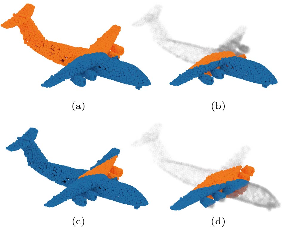
We extract the boundary between each point cloud pair to train our PuzzleNet. Because there is no clear definition of the boundary between point clouds, manually labeling is extremely time-consuming. We choose to filter the boundary by the point-wise distance between point clouds. We firstly calculate the pairwise distance by d_{b} (\boldsymbol S_1, \boldsymbol S_2) = \sum_{x\in \boldsymbol S_1}\min_{y\in \boldsymbol S_2} {\lVert x-y \rVert}^2_2 , and we sort d_b in ascending order. Then we choose the first N^B points as the boundary points. As illustrated in Fig.5, we calculate the distance and sort the points in ascending order (see Figs.5(a) and 5(b)), where points with darker colors are closer to the neighboring point cloud. Then different N^B of 64, 128 and 256 are shown in Figs.5(c)–5(e) respectively. We empirically set N^B=128 in all of our experiments.
6. Experimental Setup and Results
6.1 Experimental Setup
6.1.1 Implementation Details
Our PuzzleNet is implemented in Pytorch on a single NVIDIA RTX 2080Ti (11 GB memory) graphics card. We train the neural network on the DublinPuzzle and ModelPuzzle-P datasets for 5000 epochs, and on our ModelPuzzle-M dataset for 10000 epochs with an Adam optimizer. The initial learning rate is set to 10^{-3} and reduced with an attenuation coefficient of 0.99 every 30 steps.
6.1.2 Evaluation Metrics
To evaluate the accuracy of our estimated transformation, we use several commonly-used metrics[43, 49] to measure the difference between ground-truth \bar{\boldsymbol{{R}}} and \bar{t} and our predicted {\boldsymbol{R}} and t. We first compute the mean isotropic rotation and translation errors by:
\begin{aligned}[b] &R_{\rm iso} = \arccos{((Tr({\boldsymbol{\bar{R}}}^{-1}{\boldsymbol{R}})-1)/2)} \text{,} \\ & t_{\rm iso} = \Vert {\boldsymbol{\bar{R}}}^{-1}{\boldsymbol{t}}-{\boldsymbol{\bar{t}}} \Vert_1 \text{,} \end{aligned} where Tr({\boldsymbol{M}}) returns the trace of a matrix M and R_{\rm iso} measures the minimum rotation angle required to align the rotations ( {\boldsymbol{\bar{R}}} and {\boldsymbol{R}} ) of two poses.
In addition, anisotropic metrics are calculated in the forms of mean squared error (mse) and mean absolute error (mae) to evaluate the absolute errors over Euler angles and translation vectors:
\begin{aligned}[b] & R_{\rm mse} = MSE( Euler({\boldsymbol{\bar{R}}}), Euler({\boldsymbol{R}}) ) \text{,}\\ & R_{\rm mae}= MAE( Euler({\boldsymbol{\bar{R}}}), Euler({\boldsymbol{R}}) ) \text{,}\\ & t_{\rm mse} = MSE( {\boldsymbol{\bar{t}}}, {\boldsymbol{t}})\text{,}\;\; t_{\rm mae} = MAE( {\boldsymbol{\bar{t}}}, {\boldsymbol{t}})\text{,} \end{aligned} where MAE(\cdot) and MSE(\cdot) are two functions to calculate mean absolute errors and mean squared errors, respectively. Euler(\cdot) calculates the corresponding Euler angles from a rotation matrix.
To determine the accuracy of boundary prediction, we adopt the metric of point-wise intersection over union (IoU) which is widely used in 3D part-segmentation. Besides, we also use the Chamfer distance to evaluate the distance between the predicted boundaries {\boldsymbol{B_P}} and {\boldsymbol{B_Q}} and the ground-truth boundary points {\boldsymbol{\hat{B_P}}} and {\boldsymbol{\hat{B_Q}}} :
\begin{align} \begin{split} CD_{P} &= d_{\rm CD}( {\boldsymbol{B_P}}, {\boldsymbol{\hat{B_P}}} ) \text{,} \quad CD_Q = d_{\rm CD}( {\boldsymbol{B_Q}}, {\boldsymbol{\hat{B_Q}}} ).\nonumber\end{split}\end{align} 6.2 Self Evaluation
6.2.1 Pairwise Shape Alignment
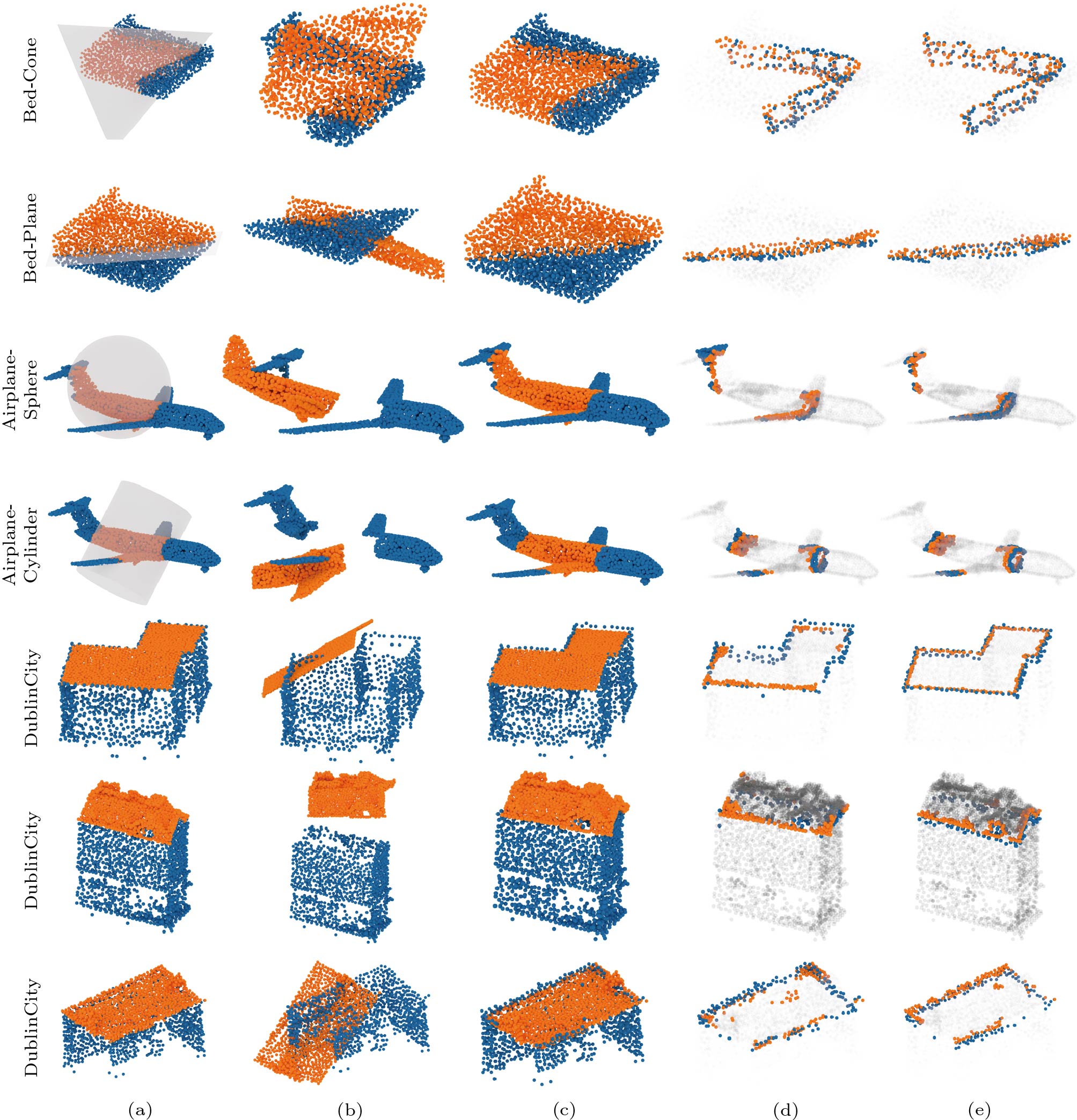
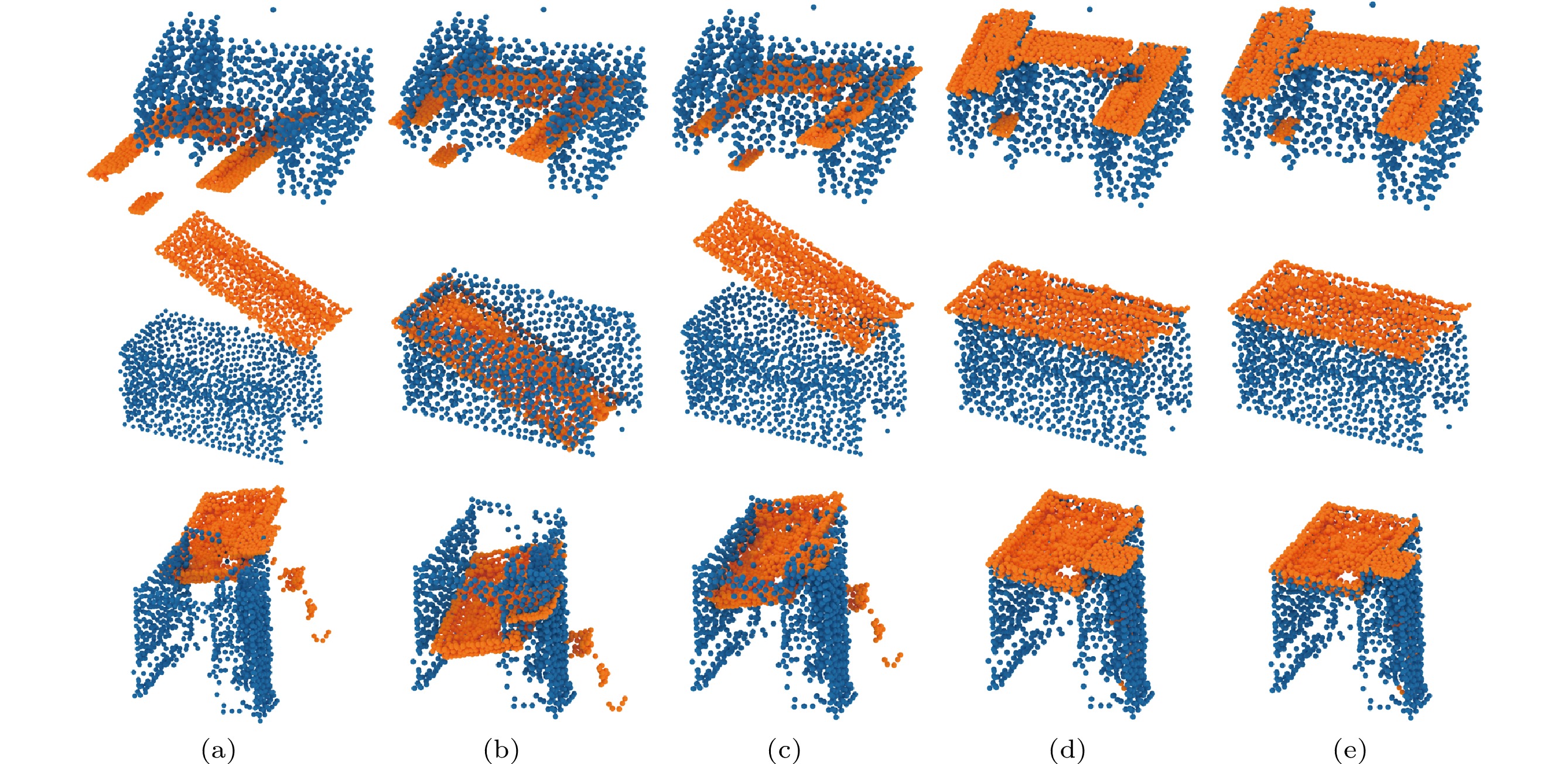
We first evaluate the performance of our PuzzleNet on pairwise geometric shape alignment. Fig.6 shows the visual shape alignment results using several point clouds from our ModelPuzzle-P (airplanes and beds) and DublinPuzzle, and we cut the CAD models using different primitives. For each example, we also illustrate the predicted boundaries to show whether our approach is able to learn effective boundary features.
![]() Figure 6. Visual results of pairwise shape alignment using beds, airplanes and Dublin buildings. For bed and airplane models, we show the cutting types using different 3D primitives (single cone, plane, sphere or cylinder) which are drawn in transparent gray. Besides, in (d) and (e) we show the predicted boundaries and ground-truth boundary points. (a) GT (ground truth). (b) Input. (c) Output. (d) Output-boundary. (e) GT-boundary.
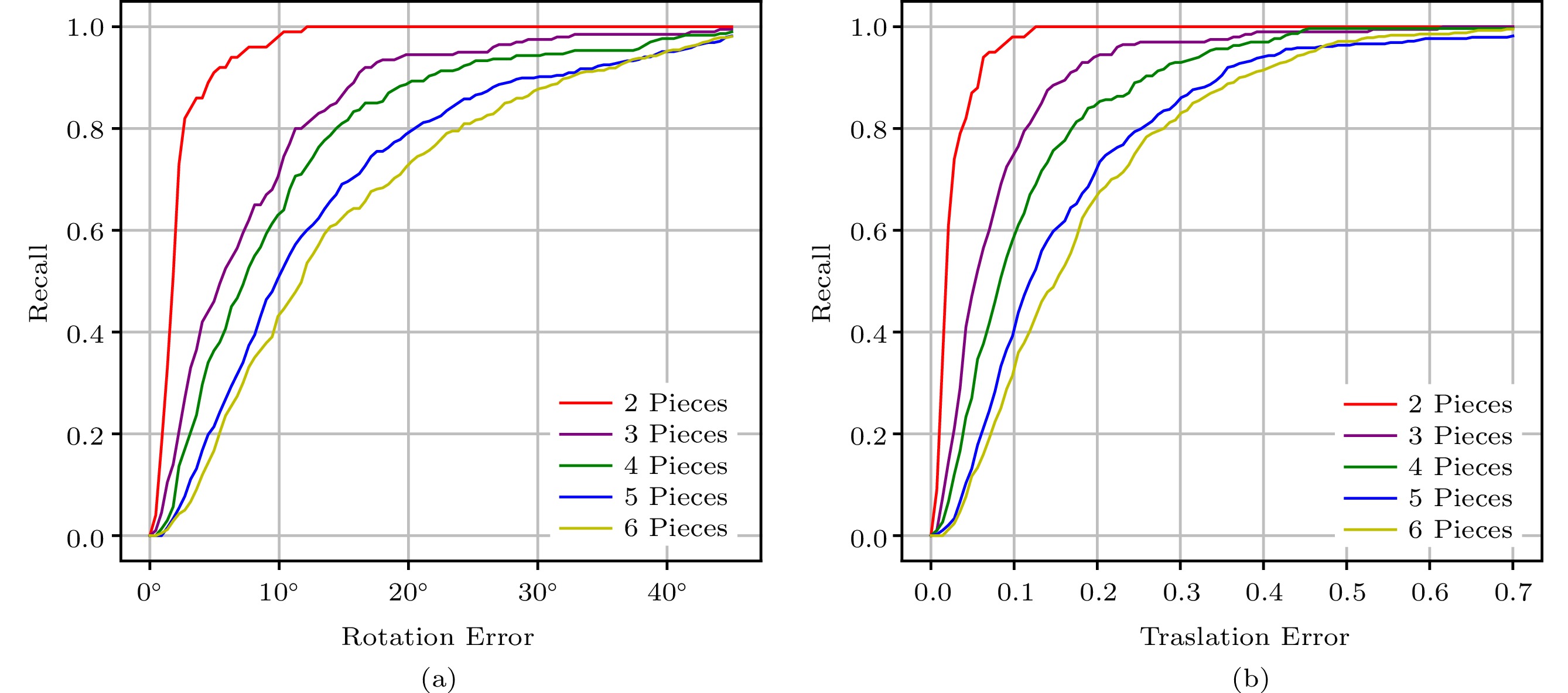
Figure 6. Visual results of pairwise shape alignment using beds, airplanes and Dublin buildings. For bed and airplane models, we show the cutting types using different 3D primitives (single cone, plane, sphere or cylinder) which are drawn in transparent gray. Besides, in (d) and (e) we show the predicted boundaries and ground-truth boundary points. (a) GT (ground truth). (b) Input. (c) Output. (d) Output-boundary. (e) GT-boundary.For quantitative evaluation, Fig.7 reports the recall as the ratio of successful alignment, where a transformation is accepted as positive if the rotation and translation errors are within the thresholds \xi_r and \xi_t respectively. Table 1 numerically evaluates the accuracy of boundary prediction. As shown in Fig.6 and Table 1, our PuzzleNet learns reasonable boundary predictions and successfully aligns the shape pieces that have no overlaps or semantic information.
Table 1. Quantitative Evaluations of Boundary PredictionDataset IoU_{\boldsymbol P} \uparrow IoU_{\boldsymbol Q} \uparrow CD_{\boldsymbol P} \downarrow CD_{\boldsymbol Q} \downarrow DublinPuzzle 0.3258 0.1784 0.0233 0.4016 Plane 0.5522 0.6640 0.0023 0.4601 Cylinder 0.7388 0.7513 0.0027 0.3788 Cone 0.6429 0.7359 0.0214 0.4407 Sphere 0.4949 0.7212 0.0260 0.3899 Note: Numerical statistics of the accuracy of boundary pre-diction were tested on our DublinPuzzle and the ModelPuzzle-P dataset under different cut types. The plane, cylinder, cone, and sphere are four different primitives to cut one single point cloud into two non-overlapping ones in our ModelPuzzle-P dataset. ↑: a higher value indicates better performance; ↓: a lower value indicates better performance. 6.2.2 Multi-Piece Assembly
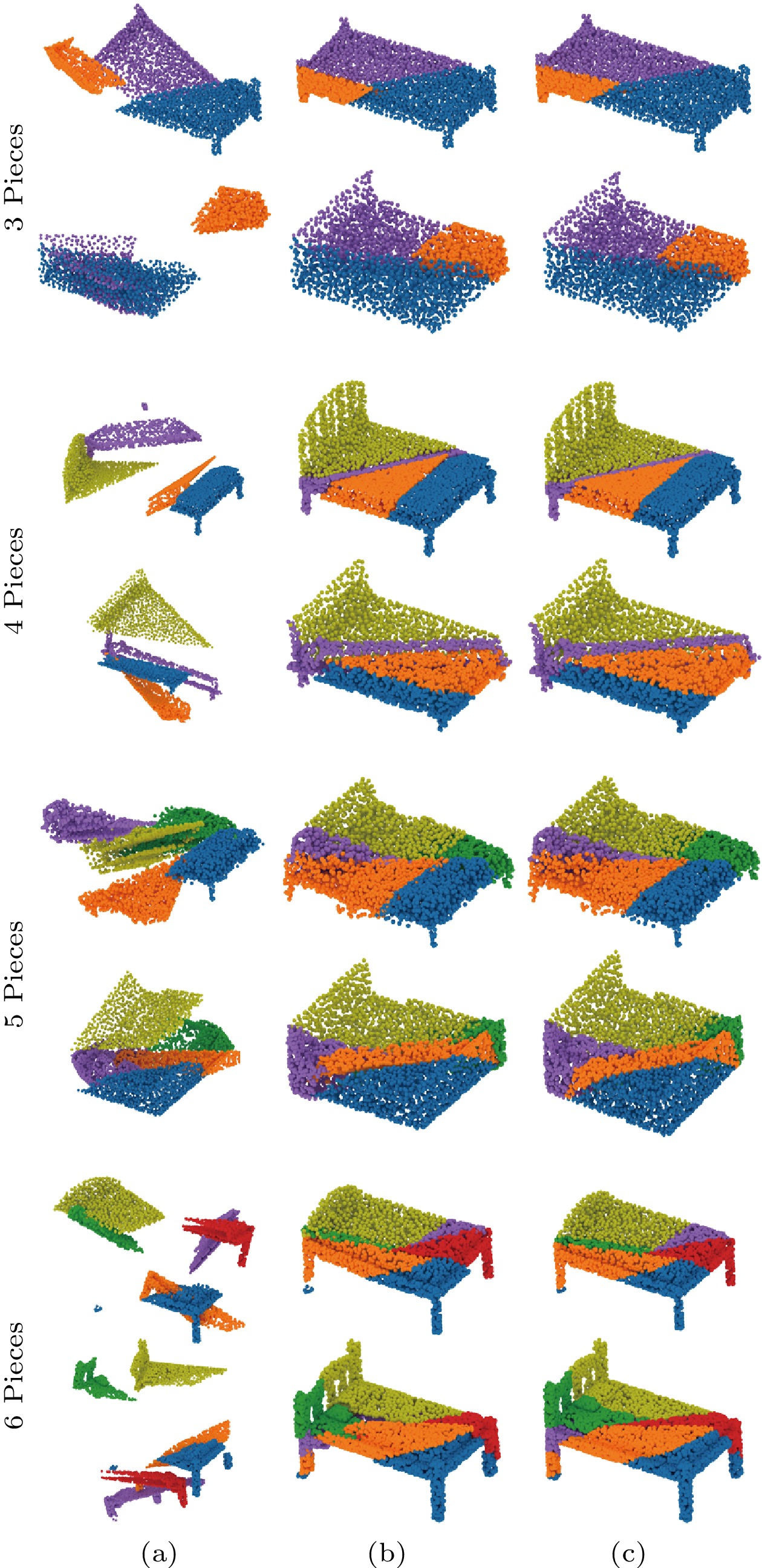
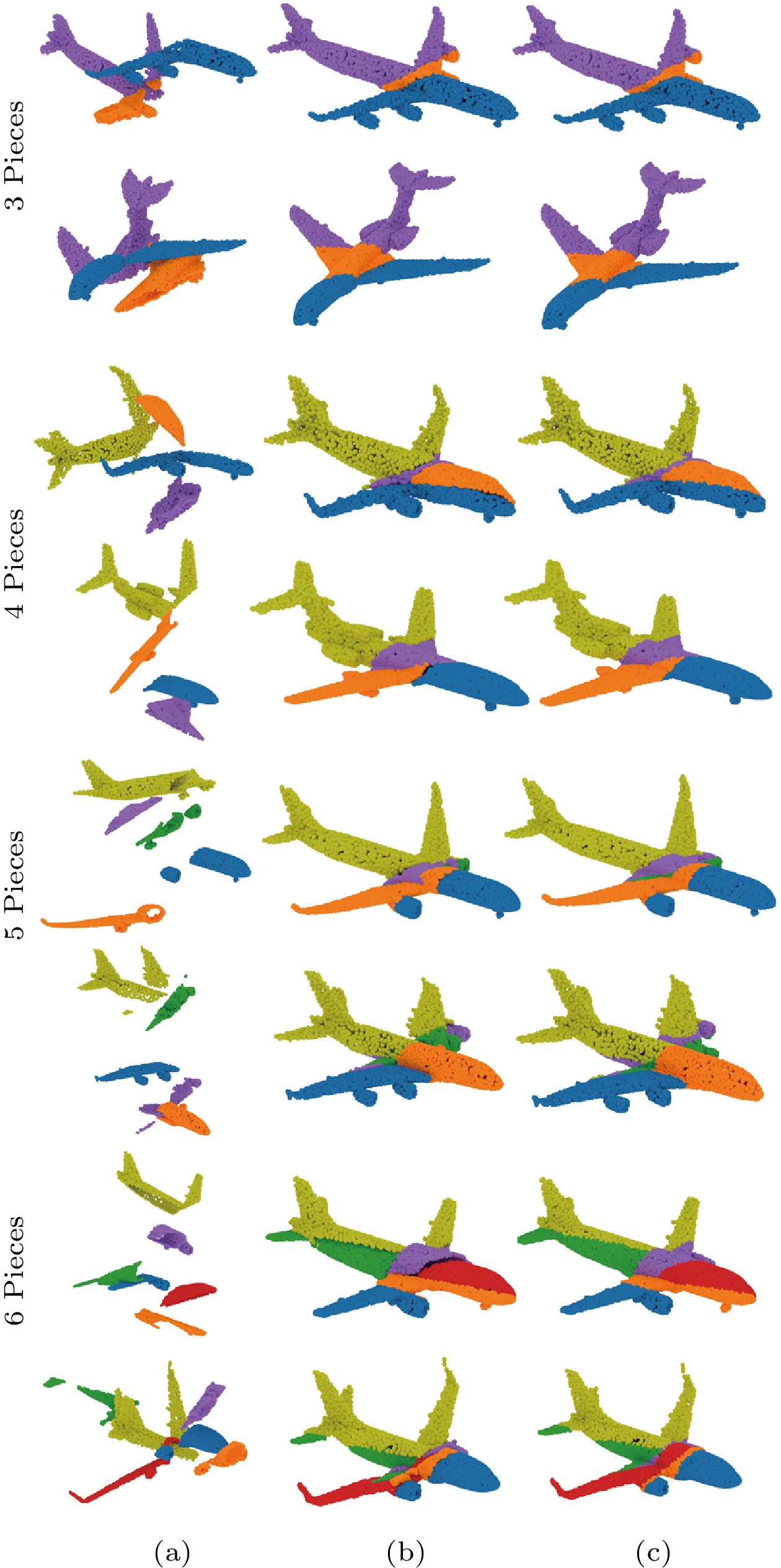
The ability to assemble multiple point clouds is gained by predicting the transformation and the boundary information simultaneously and then choosing the most reasonable one from many candidates by comparing the distance between the boundaries of each pair. We train PuzzleNet only on our ModelPuzzle-M dataset with four pieces and test it on other multi-piece cases. Fig.7 illustrates the quantitative evaluation. Fig.8 and Fig.9 show the visual assembling results. Table 2 reports the recall performance value on several specific thresholds. Figs.7-9 and Table 2 mentioned above demonstrate the robustness of our PuzzleNet against a different number of input pieces.
![]() Figure 8. Visual results of our multi-piece assembly—two sample beds. We test our approach on our ModelPuzzle-M dataset where the number of input pieces ranges from 3 to 6. For each case, we select two beds and show (a) input point clouds, (b) our assembling results, and (c) the ground truth, respectively.
Figure 8. Visual results of our multi-piece assembly—two sample beds. We test our approach on our ModelPuzzle-M dataset where the number of input pieces ranges from 3 to 6. For each case, we select two beds and show (a) input point clouds, (b) our assembling results, and (c) the ground truth, respectively.![]() Figure 9. Visual results of our multi-piece assembly—two sample airplanes. We test our approach on our ModelPuzzle-M dataset where the number of input pieces ranges from 3 to 6. For each example, we select two airplanes and show (a) input point clouds, (b) our assembling results, and (c) the ground truth, respectively.Table 2. Recall Performance on Several Specific Thresholds
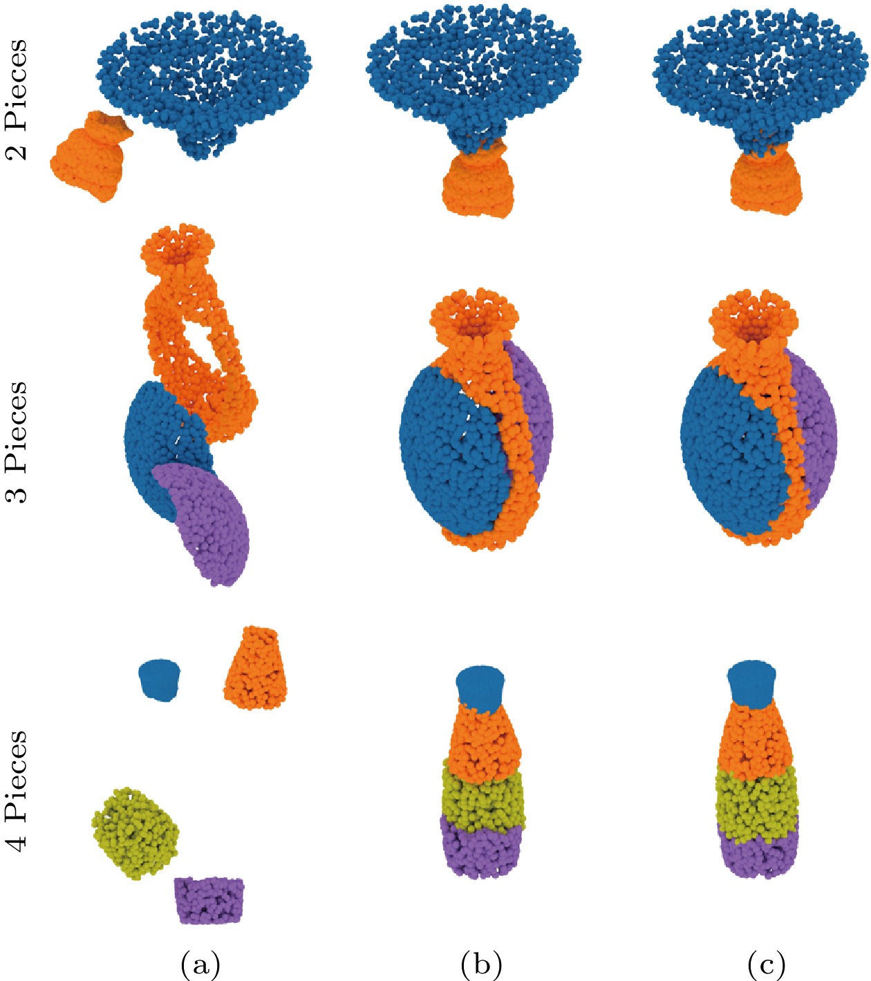
Figure 9. Visual results of our multi-piece assembly—two sample airplanes. We test our approach on our ModelPuzzle-M dataset where the number of input pieces ranges from 3 to 6. For each example, we select two airplanes and show (a) input point clouds, (b) our assembling results, and (c) the ground truth, respectively.Table 2. Recall Performance on Several Specific ThresholdsNumber of Pieces R_{\rm err}=15 t_{\rm err}=0.15 2 1.0000 0.9800 3 0.8700 0.7600 4 0.8100 0.5833 5 0.6907 0.4046 6 0.6283 0.3238 Note: Rerr: rotation error; terr: translation error. Furthermore, to test the robustness of PuzzleNet against different cutting types, we select the category of the vase from our ModelPuzzle-M and train PuzzleNet on the dataset constructed by using our cutting approach (see Section 5). To prepare the testing data, we simulate the realistic breaking results of the vase models by using the method proposed by [50] to simulate the most natural ways to break the object. Thus the broken way of such models is different from that of our training data. Fig.10 shows the assembling results of our PuzzleNet, indicating that we still achieve promising outcomes.
![]() Figure 10. PuzzleNet can be applied to assemble 3D shapes that are broken by different cutting approaches, such as using the realistic breaking simulation method[50]. (a) Input. (b) Output. (c) Ground truth.
Figure 10. PuzzleNet can be applied to assemble 3D shapes that are broken by different cutting approaches, such as using the realistic breaking simulation method[50]. (a) Input. (b) Output. (c) Ground truth.6.3 Comparisons
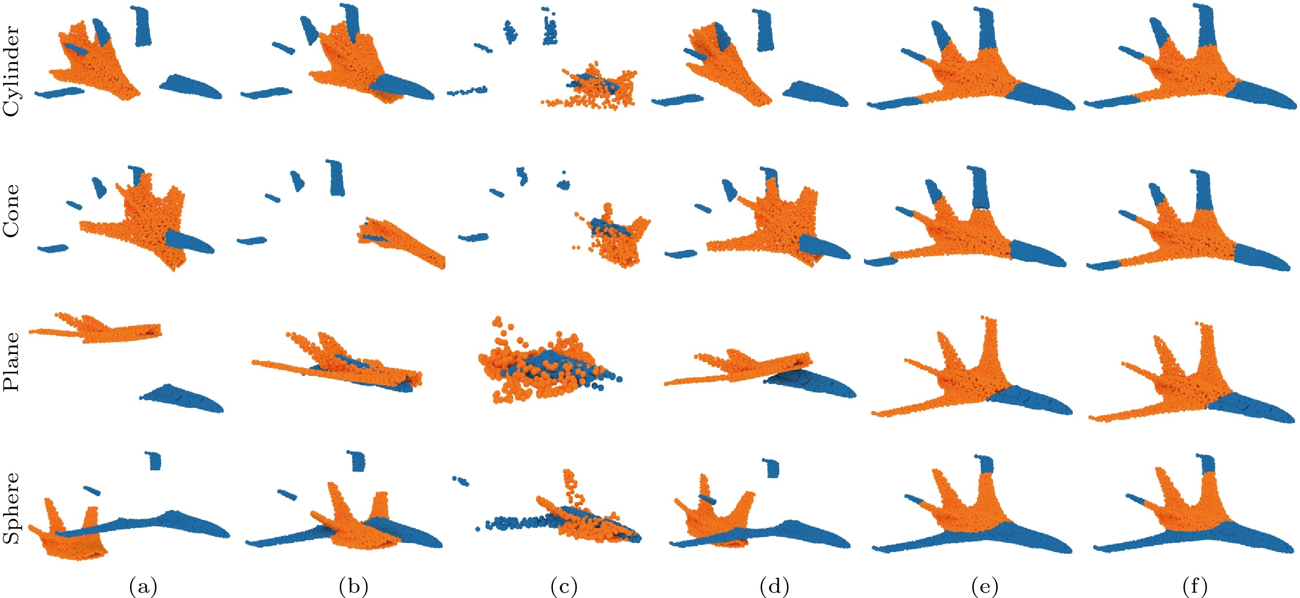
We compare our method against both point cloud registration and shape mating methods. Neural Shape Mating (NSM)[4] is the most recent method that comes closest to our task setting, i.e., it is based on supervised learning and addresses non-overlapping point cloud assembly. Therefore, we select it as the main competitor. Since point cloud registration and shape assembly share a similar problem of pose prediction, we also compare our method with two registration methods, including a global registration method, Fast Global Registration (FGR)[23], and a learning-based method, PREDATOR[10]. Actually, our problem will reduce to point cloud alignment if additional information (e.g., interface segmentation or boundary extraction) is available. To relieve the dependence on points overlapping, we particularly select PREDATOR[10], which is the recent state-of-the-art learning-based low-overlap registration method.
For a fair comparison, we re-train NSM[4] on the category of airplanes from our ModelPuzzle-P and DublinPuzzle datasets. Note that as PREDATOR[10] still relies on overlap information, we fail to train a valid network on our datasets. Thus, we use the officially released PREDATOR model with weights trained on ModelNet40, and we compare our approach with it using airplane shapes. Furthermore, we only compare these methods on pairwise registration/mating, because they cannot handle multi-piece assembly.
Figs.11 and 12 show the qualitative comparison results on airplanes of our ModelPuzzle-P and DublinPuzzle datasets, respectively. Previous registration methods[10, 23] fail when matching geometric features without overlapping regions. Instead, they attempt to overlay pieces by trying to find overlapping point-pairs for further optimization. Compared with NSM, our PuzzleNet achieves more accurate shape mating results. The quantitative comparison is provided in Table 3. We outperform all the handcrafted and learning methods by a large margin in both rotation and translation prediction.
![]() Figure 11. Visual comparison of our approach with FGR[23], Predator[10] and NSM[4] for pairwise shape mating. We test the methods on the category of airplane from our ModelPuzzle-P dataset which is cut by using different 3D cutting primitives. (a) Input. (b) FGR[23]. (c) Predator[10]. (d) NSM[4]. (e) Ours. (f) Ground truth.Table 3. Quantitative Comparison of Different Methods for Pairwise Shape Alignment
Figure 11. Visual comparison of our approach with FGR[23], Predator[10] and NSM[4] for pairwise shape mating. We test the methods on the category of airplane from our ModelPuzzle-P dataset which is cut by using different 3D cutting primitives. (a) Input. (b) FGR[23]. (c) Predator[10]. (d) NSM[4]. (e) Ours. (f) Ground truth.Table 3. Quantitative Comparison of Different Methods for Pairwise Shape AlignmentDataset Method R_{\rm iso} \downarrow t_{\rm iso} \downarrow R_{\rm mse} \downarrow R_{\rm mae} \downarrow t_{\rm mse} \downarrow t_{\rm mae} \downarrow DublinPuzzle FGR[23] 39.8084 0.8332 770.4874 20.1878 0.2660 0.4169 NSM[4] 29.5259 0.3260 324.4744 14.6914 0.0398 0.1626 PuzzleNet 7.2873 0.0764 30.4020 3.6528 0.0028 0.0379 Plane FGR[23] 79.0867 0.9084 4452.1583 41.8482 0.3144 0.4592 Predator[10] 71.1062 0.5575 2750.7584 37.3222 0.1331 0.2510 NSM[4] 25.6709 0.4004 252.2779 12.7266 0.0609 0.1958 PuzzleNet 2.2049 0.0251 2.9568 1.0631 0.0004 0.0121 Cylinder FGR[23] 65.2692 0.8421 3590.8886 36.4658 0.2667 0.4215 Predator[10] 60.5815 0.5477 1722.9497 30.8506 0.1201 0.2486 NSM[4] 31.4569 0.2999 366.0138 16.0299 0.0326 0.1505 PuzzleNet 1.6524 0.0172 2.3867 0.8269 0.0003 0.0085 Cone FGR[23] 49.1665 0.8197 2081.8663 27.3513 0.2613 0.4062 Predator[10] 60.6906 0.6908 1792.4524 31.8404 0.1866 0.3113 NSM[4] 27.2779 0.3786 278.4967 13.7801 0.0560 0.1906 PuzzleNet 3.1074 0.0312 5.2512 1.5822 0.0006 0.0155 Sphere FGR[23] 87.4699 0.7973 4783.8691 43.8576 0.2446 0.3984 Predator[10] 65.0936 0.5627 2079.1263 31.7647 0.1359 0.2549 NSM[4] 31.7505 0.3219 376.8902 15.8825 0.0396 0.1617 PuzzleNet 2.2254 0.0199 3.6674 1.0985 0.0003 0.0101 Note: We test the methods on the DublinPuzzle dataset and the category of airplane from our ModelPuzzle-P dataset which is cut by using different 3D cutting primitives (i.e., plane, cylinder, cone, and sphere). The best results of each measurement are marked in bold. 6.4 Ablation Study
We present ablation studies to verify the effectiveness of the designed framework.
6.4.1 Loss Functions
We first evaluate the effectiveness of different losses used in our network. Without loss of generality, we use the category of airplane cut by the plane primitive for conducting an ablation study.
Table 4 shows the accuracy of transformation estimation of our PuzzleNet which is trained with different combinations of losses. As we can see, the L_{\rm MSE} loss plays an important role in reducing rotation errors while L_{\rm EMD} achieves a better translation accuracy. Although using L_{\rm CD} alone cannot obtain satisfactory results, it enhances the capability of improving both the rotation and translation accuracy. Overall, the combination of three losses achieves the best performance.
Table 4. Quantitative Evaluation of Different Loss Functions on the Effect of Transformation EstimationL_{\rm MSE} L_{\rm CD} L_{\rm EMD} R_{\rm mse} \downarrow t_{\rm mse} \downarrow R_{\rm iso} \downarrow t_{\rm iso} \downarrow \checkmark 4.0198 0.0007 1.9487 0.0295 \checkmark 9.3231 0.0013 2.8730 0.0422 \checkmark 4.6257 0.0005 2.4934 0.0258 \checkmark \checkmark 3.1079 0.0005 1.7379 0.0281 \checkmark \checkmark \checkmark 2.9568 0.0004 2.2049 0.0251 Note: This ablation study is conducted on the category of the airplane from our ModelPuzzle-P dataset cut by the plane primitive. The best results of each measurement are marked in bold. 6.4.2 Multi-Task Network
To prove that the two decoders in Fig.2 do not affect each other, we train two independent networks for transformation and boundary prediction, respectively. All networks are trained using the same point cloud encoder, parameters, and epochs. The performance of transformation and boundary prediction is summarized in Table 5. In terms of rotation and translation errors, the transformation estimation results of our proposed joint network are better than those of only training a transformation network. At the same time, we do not reduce the accuracy of boundary prediction too much (see IoU_P and IoU_Q in Table 5).
Table 5. Ablation Study of Our Multi-Task Neural Network with Different Combinations of Two BranchesTrans.Branch Bound.Branch R_{\rm iso} \downarrow t_{\rm iso} \downarrow IoU_P \uparrow IoU_Q \uparrow \checkmark 2.9178 0.0324 \checkmark 0.5653 0.7169 \checkmark \checkmark 2.2049 0.0251 0.5522 0.6640 Note: We test different combinations of two branches in our network. The two branches are transformation branch (Trans.Branch) and boundary branch (Bound.Branch). We use the category of airplane cut by the plane primitive from our ModelPuzzle-P dataset. Since the two decoders in our joint neural network use the same point cloud encoder, they can simultaneously have influence on the weights of the encoder. Therefore, by balancing the two decoders, our network are more stable compared with the two independent networks. In addition, as we propose an end-to-end solution, our proposed method is also more efficient than training two independent networks.
6.5 Discussion
While producing convincing results, our framework still has several limitations. First, our multi-piece reassembling method relies on minimizing the errors between each pair of pieces locally. Thus, the deviation will be accumulated in the process of reassembling point clouds piece by piece, taking Fig.13 as an example. Actually, the performance of our approach is relatively stable when the number of pieces is less than 6. While the number of pieces is large, the accumulated deviation will cause the fluctuation of the assembling results, which will decrease the recall performance. To tackle this problem, a global optimization approach is required, which is still not trivial considering the non-overlap scenarios.
The second limitation is that we may not properly handle pieces with similar cutting boundaries. This case can cause ambiguous piece assembly and requires global information to determine which one is optimal. At last, like most learning-based methods for shape analysis, PuzzleNet is still category-specific and relies on the pre-collected and labeled dataset. That is to say, the neural model trained on one category cannot be used for assembling the shapes of another category.
7. Conclusions
We advanced 3D shape assembly by introducing PuzzleNet, a deep neural network for learning to assemble non-overlapping point clouds by using purely geometric information. Inspired by puzzle solving, PuzzleNet learns accurate pairwise alignment by inferring the rigid transformation and boundary features simultaneously, where two decoders are carefully designed in a unified network to remain unaffected by each other. Benefiting from the boundary feature learning and matching, the multi-piece assembly can be easily achieved by an iterative greedy algorithm. We demonstrated the effectiveness and advantages of our approach by comparing it with state-of-the-art (SOTA) methods on synthetic and real-scanned datasets, where our method has surpassed the SOTA methods by more than 10 times in rotation metrics and four times in translation metrics.
In the future, we would like to study real-world multi-piece assembling by expanding our datasets with more realistic breaking shapes of complex and arbitrary cutting boundaries. We also plan to extend PuzzleNet to learn end-to-end multi-piece assembly.
-
Figure 1. PuzzleNet designed to automatically assemble complete shapes from multiple pieces. Given (a) four geometric pieces, (b) PuzzleNet learns pairwise shape alignment by predicting the transformation and the boundary information. (c) Then we achieve a full 3D shape by iteratively computing a global multi-piece assembly based on the distance between the boundaries of each pair.
Figure 2. Network architecture of our proposed PuzzleNet. We apply a transformer-based encoder to extract both global and local geometric features, which are then passed to two decoders to estimate a rigid transformation and predict the boundary respectively. The number of output channels is shown above the corresponding modules.
Figure 3. Illustration of our multi-piece assembly process. (a) Input: four pieces of point clouds. (b) Assembly result after the first iteration (iteration 1). (c) Assembly result after the second iteration (iteration 2). (d) Final assembly result after the third iteration (output). (e) Ground-truth assembly. (f) Detailed process of iteration 1. PuzzleNet is first applied to predict pairwise rigid pose and boundary points. Then we select the best alignment with the minimum distance between the boundary points. The selected two pieces are merged together and involved in later iterations.
Figure 6. Visual results of pairwise shape alignment using beds, airplanes and Dublin buildings. For bed and airplane models, we show the cutting types using different 3D primitives (single cone, plane, sphere or cylinder) which are drawn in transparent gray. Besides, in (d) and (e) we show the predicted boundaries and ground-truth boundary points. (a) GT (ground truth). (b) Input. (c) Output. (d) Output-boundary. (e) GT-boundary.
Figure 8. Visual results of our multi-piece assembly—two sample beds. We test our approach on our ModelPuzzle-M dataset where the number of input pieces ranges from 3 to 6. For each case, we select two beds and show (a) input point clouds, (b) our assembling results, and (c) the ground truth, respectively.
Figure 9. Visual results of our multi-piece assembly—two sample airplanes. We test our approach on our ModelPuzzle-M dataset where the number of input pieces ranges from 3 to 6. For each example, we select two airplanes and show (a) input point clouds, (b) our assembling results, and (c) the ground truth, respectively.
Figure 10. PuzzleNet can be applied to assemble 3D shapes that are broken by different cutting approaches, such as using the realistic breaking simulation method[50]. (a) Input. (b) Output. (c) Ground truth.
Figure 11. Visual comparison of our approach with FGR[23], Predator[10] and NSM[4] for pairwise shape mating. We test the methods on the category of airplane from our ModelPuzzle-P dataset which is cut by using different 3D cutting primitives. (a) Input. (b) FGR[23]. (c) Predator[10]. (d) NSM[4]. (e) Ours. (f) Ground truth.
Algorithm 1. Multi-Pieces Assembly Input: n pieces of unassembled point clouds S_P = \{P_{1}, P_{2},\ \dots,\ P_{n} \} Output: point cloud S_P^\prime representing the reassembled complete shape 1: n_{S} \gets 0 2: for P_i \in S_P do 3: S_i \gets MAKE-SET(P_i) //make a set 4: n_S \gets n_{S} + 1 5: end for 6: S_P \gets \{S_1, S_2, \dots, S_i, \dots, S_n\} 7: while n_{S} > 1 do 8: D_i^j \gets \{ \} 9: for S_i \gets \{S_1, \dots, S_{n-1} \} do 10: for S_j \gets \{S_{i+1}, \dots, S_{n} \} do 11: {\boldsymbol{T}}_i^j, d_i^j \gets PuzzleNET(FPS(S_i), FPS(S_j)) 12: D_i^j.add(d_i^j) 13: end for 14: end for 15: S_i, S_j \gets {\rm min}(\{D_i^j\}) 16: S_P.pop(S_i); S_P.pop(S_j) 17: S_P.add(UNION(S_i, S_j \cdot {\boldsymbol{T}}_i^j)) 18: n_S \gets n_S - 1 19: end while 20: S_P^\prime \gets\;S_P.pop(S_1) return S_P^\prime Table 1 Quantitative Evaluations of Boundary Prediction
Dataset IoU_{\boldsymbol P} \uparrow IoU_{\boldsymbol Q} \uparrow CD_{\boldsymbol P} \downarrow CD_{\boldsymbol Q} \downarrow DublinPuzzle 0.3258 0.1784 0.0233 0.4016 Plane 0.5522 0.6640 0.0023 0.4601 Cylinder 0.7388 0.7513 0.0027 0.3788 Cone 0.6429 0.7359 0.0214 0.4407 Sphere 0.4949 0.7212 0.0260 0.3899 Note: Numerical statistics of the accuracy of boundary pre-diction were tested on our DublinPuzzle and the ModelPuzzle-P dataset under different cut types. The plane, cylinder, cone, and sphere are four different primitives to cut one single point cloud into two non-overlapping ones in our ModelPuzzle-P dataset. ↑: a higher value indicates better performance; ↓: a lower value indicates better performance. Table 2 Recall Performance on Several Specific Thresholds
Number of Pieces R_{\rm err}=15 t_{\rm err}=0.15 2 1.0000 0.9800 3 0.8700 0.7600 4 0.8100 0.5833 5 0.6907 0.4046 6 0.6283 0.3238 Note: Rerr: rotation error; terr: translation error. Table 3 Quantitative Comparison of Different Methods for Pairwise Shape Alignment
Dataset Method R_{\rm iso} \downarrow t_{\rm iso} \downarrow R_{\rm mse} \downarrow R_{\rm mae} \downarrow t_{\rm mse} \downarrow t_{\rm mae} \downarrow DublinPuzzle FGR[23] 39.8084 0.8332 770.4874 20.1878 0.2660 0.4169 NSM[4] 29.5259 0.3260 324.4744 14.6914 0.0398 0.1626 PuzzleNet 7.2873 0.0764 30.4020 3.6528 0.0028 0.0379 Plane FGR[23] 79.0867 0.9084 4452.1583 41.8482 0.3144 0.4592 Predator[10] 71.1062 0.5575 2750.7584 37.3222 0.1331 0.2510 NSM[4] 25.6709 0.4004 252.2779 12.7266 0.0609 0.1958 PuzzleNet 2.2049 0.0251 2.9568 1.0631 0.0004 0.0121 Cylinder FGR[23] 65.2692 0.8421 3590.8886 36.4658 0.2667 0.4215 Predator[10] 60.5815 0.5477 1722.9497 30.8506 0.1201 0.2486 NSM[4] 31.4569 0.2999 366.0138 16.0299 0.0326 0.1505 PuzzleNet 1.6524 0.0172 2.3867 0.8269 0.0003 0.0085 Cone FGR[23] 49.1665 0.8197 2081.8663 27.3513 0.2613 0.4062 Predator[10] 60.6906 0.6908 1792.4524 31.8404 0.1866 0.3113 NSM[4] 27.2779 0.3786 278.4967 13.7801 0.0560 0.1906 PuzzleNet 3.1074 0.0312 5.2512 1.5822 0.0006 0.0155 Sphere FGR[23] 87.4699 0.7973 4783.8691 43.8576 0.2446 0.3984 Predator[10] 65.0936 0.5627 2079.1263 31.7647 0.1359 0.2549 NSM[4] 31.7505 0.3219 376.8902 15.8825 0.0396 0.1617 PuzzleNet 2.2254 0.0199 3.6674 1.0985 0.0003 0.0101 Note: We test the methods on the DublinPuzzle dataset and the category of airplane from our ModelPuzzle-P dataset which is cut by using different 3D cutting primitives (i.e., plane, cylinder, cone, and sphere). The best results of each measurement are marked in bold. Table 4 Quantitative Evaluation of Different Loss Functions on the Effect of Transformation Estimation
L_{\rm MSE} L_{\rm CD} L_{\rm EMD} R_{\rm mse} \downarrow t_{\rm mse} \downarrow R_{\rm iso} \downarrow t_{\rm iso} \downarrow \checkmark 4.0198 0.0007 1.9487 0.0295 \checkmark 9.3231 0.0013 2.8730 0.0422 \checkmark 4.6257 0.0005 2.4934 0.0258 \checkmark \checkmark 3.1079 0.0005 1.7379 0.0281 \checkmark \checkmark \checkmark 2.9568 0.0004 2.2049 0.0251 Note: This ablation study is conducted on the category of the airplane from our ModelPuzzle-P dataset cut by the plane primitive. The best results of each measurement are marked in bold. Table 5 Ablation Study of Our Multi-Task Neural Network with Different Combinations of Two Branches
Trans.Branch Bound.Branch R_{\rm iso} \downarrow t_{\rm iso} \downarrow IoU_P \uparrow IoU_Q \uparrow \checkmark 2.9178 0.0324 \checkmark 0.5653 0.7169 \checkmark \checkmark 2.2049 0.0251 0.5522 0.6640 Note: We test different combinations of two branches in our network. The two branches are transformation branch (Trans.Branch) and boundary branch (Bound.Branch). We use the category of airplane cut by the plane primitive from our ModelPuzzle-P dataset. -
[1] Funkhouser T, Kazhdan M, Shilane P, Min P, Kiefer W, Tal A, Rusinkiewicz S, Dobkin D. Modeling by example. ACM Trans. Graphics, 2004, 23(3): 652–663. DOI: 10.1145/1015706.1015775.
[2] Huang Q X, Flöry S, Gelfand N, Hofer M, Pottmann H. Reassembling fractured objects by geometric matching. ACM Trans. Graphics, 2006, 25(3): 569–578. DOI: 10.1145/1141911.1141925.
[3] Wu K, Fu X M, Chen R J, Liu L G. Survey on computational 3D visual optical art design. Visual Computing for Industry, Biomedicine, and Art, 2022, 5(1): Article No. 31. DOI: 10.1186/s42492-022-00126-z.
[4] Chen Y C, Li H D, Turpin D, Jacobson A, Garg A. Neural shape mating: Self-supervised object assembly with adversarial shape priors. In Proc. the 2022 IEEE/CVF Conference on Computer Vision and Pattern Recognition, Jun. 2022, pp.12724–12733. DOI: 10.1109/CVPR52688.2022.01239.
[5] Huang H, Gong M L, Cohen-Or D, Ouyang Y B, Tan F W, Zhang H. Field-guided registration for feature-conforming shape composition. ACM Trans. Graphics, 2012, 31(6): Article No. 179. DOI: 10.1145/2366145.2366198.
[6] Huang J, Zhan G Q, Fan Q N, Mo K C, Shao L, Chen B Q, Guibas L J, Dong H. Generative 3D part assembly via dynamic graph learning. In Proc. the 34th International Conference on Neural Information Processing Systems, Dec. 2020.
[7] Li Y C, Mo K C, Shao L, Sung M, Guibas L. Learning 3D part assembly from a single image. In Proc. the 16th European Conference on Computer Vision, Aug. 2020, pp.664–682. DOI: 10.1007/978-3-030-58539-6_40.
[8] Lee Y, Hu E S, Lim J J. IKEA furniture assembly environment for long-horizon complex manipulation tasks. In Proc. the 2021 IEEE International Conference on Robotics and Automation, Jun. 2021, pp.6343–6349. DOI: 10.1109/ICRA48506.2021.9560986.
[9] Huang X S, Mei G F, Zhang J, Abbas R. A comprehensive survey on point cloud registration. arXiv: 2103.02690, 2021. https://arxiv.org/abs/2103.02690, Jun. 2023.
[10] Huang S Y, Gojcic Z, Usvyatsov M, Wieser A, Schindler K. PREDATOR: Registration of 3D point clouds with low overlap. In Proc. the 2021 IEEE/CVF Conference on Computer Vision and Pattern Recognition, Jun. 2021, pp.4267–4276. DOI: 10.1109/CVPR46437.2021.00425.
[11] Qin Z, Yu H, Wang C J, Guo Y L, Peng Y X, Xu K. Geometric transformer for fast and robust point cloud registration. In Proc. the 2022 IEEE/CVF Conference on Computer Vision and Pattern Recognition, Jun. 2022, pp.11133–11142. DOI: 10.1109/CVPR52688.2022.01086.
[12] Zolanvari S M I, Ruano S, Rana A, Cummins A, da Silva R E, Rahbar M, Smolic A. DublinCity: Annotated LiDAR point cloud and its applications. In Proc. the 30th British Machine Vision Conference, Sept. 2019.
[13] Wu Z R, Song S R, Khosla A, Yu F, Zhang L G, Tang X O, Xiao J X. 3D ShapeNets: A deep representation for volumetric shapes. In Proc. the 2015 IEEE Conference on Computer Vision and Pattern Recognition, Jun. 2015, pp.1912–1920. DOI: 10.1109/CVPR.2015.7298801.
[14] Yin K X, Chen Z Q, Chaudhuri S, Fisher M, Kim V G, Zhang H. COALESCE: Component assembly by learning to synthesize connections. In Proc. the 2020 International Conference on 3D Vision, Nov. 2020. DOI: 10.1109/3DV50981.2020.00016.
[15] Willis K D D, Jayaraman P K, Chu H, Tian Y S, Li Y F, Grandi D, Sanghi A, Tran L, Lambourne J G, Solar-Lezama A, Matusik W. JoinABLe: Learning bottom-up assembly of parametric CAD joints. In Proc. the 2022 IEEE/CVF Conference on Computer Vision and Pattern Recognition, Jun. 2022. DOI: 10.1109/CVPR52688.2022.01539.
[16] Jones B, Hildreth D, Chen D W, Baran I, Kim V G, Schulz A. AutoMate: A dataset and learning approach for automatic mating of CAD assemblies. ACM Trans. Graphics, 2021, 40(6): Article No. 227. DOI: 10.1145/3478513.3480562.
[17] Jones R K, Barton T, Xu X H, Wang K, Jiang E, Guerrero P, Mitra N J, Ritchie D. ShapeAssembly: Learning to generate programs for 3D shape structure synthesis. ACM Trans. Graphics, 2020, 39(6): Article No. 234. DOI: 10.1145/3414685.3417812.
[18] Harish A N, Nagar R, Raman S. RGL-NET: A recurrent graph learning framework for progressive part assembly. In Proc. the 2022 IEEE/CVF Winter Conference on Applications of Computer Vision, Jan. 2022, pp.647–656. DOI: 10.1109/WACV51458.2022.00072.
[19] Mo K C, Zhu S L, Chang A X, Yi L, Tripathi S, Guibas L J, Su H. PartNet: A large-scale benchmark for fine-grained and hierarchical part-level 3D object understanding. In Proc. the 2019 IEEE/CVF Conference on Computer Vision and Pattern Recognition, Jun. 2019, pp.909–918. DOI: 10.1109/CVPR.2019.00100.
[20] Hong J H, Yoo S J, Zeeshan M A, Kim Y M, Kim J. Structure-from-sherds: Incremental 3D reassembly of axially symmetric pots from unordered and mixed fragment collections. In Proc. the 2021 IEEE/CVF International Conference on Computer Vision, Oct. 2021, pp.5423–5431. DOI: 10.1109/ICCV48922.2021.00539.
[21] Zhang K, Yu W Y, Manhein M, Waggenspack W, Li X. 3D fragment reassembly using integrated template guidance and fracture-region matching. In Proc. the 2015 IEEE International Conference on Computer Vision, Dec. 2015, pp.2138–2146. DOI: 10.1109/ICCV.2015.247.
[22] Aiger D, Mitra N J, Cohen-Or D. 4-points congruent sets for robust pairwise surface registration. ACM Trans. Graphics, 2008, 27(3): 1–10. DOI: 10.1145/1360612.1360684.
[23] Zhou Q Y, Park J, Koltun V. Fast global registration. In Proc. the 14th European Conference on Computer Vision, Oct. 2016, pp.766–782. DOI: 10.1007/978-3-319-46475-6_47.
[24] Mellado N, Aiger D, Mitra N J. Super 4PCS fast global pointcloud registration via smart indexing. Computer Graphics Forum, 2014, 33(5): 205–215. DOI: 10.1111/cgf.12446.
[25] Guo J W, Xing X J, Quan W Z, Yan D M, Gu Q Y, Liu Y, Zhang X P. Efficient center voting for object detection and 6D pose estimation in 3D point cloud. IEEE Trans. Image Processing, 2021, 30: 5072–5084. DOI: 10.1109/TIP.2021.3078109.
[26] Xing X J, Guo J W, Nan L L, Gu Q Y, Zhang X P, Yan D M. Efficient MSPSO sampling for object detection and 6-D pose estimation in 3-D scenes. IEEE Trans. Industrial Electronics, 2022, 69(10): 10281–10291. DOI: 10.1109/TIE.2021.3121721.
[27] Chen S L, Nan L L, Xia R B, Zhao J B, Wonka P. PLADE: A plane-based descriptor for point cloud registration with small overlap. IEEE Trans. Geoscience and Remote Sensing, 2020, 58(4): 2530–2540. DOI: 10.1109/TGRS.2019.2952086.
[28] Zhang L, Guo J W, Cheng Z L, Xiao J, Zhang X P. Efficient pairwise 3-D registration of urban scenes via hybrid structural descriptors. IEEE Trans. Geoscience and Remote Sensing, 2022, 60: Article No. 5700717. DOI: 10.1109/TGRS.2021.3091380.
[29] Fischler M A, Bolles R C. Random sample consensus: A paradigm for model fitting with applications to image analysis and automated cartography. Communications of the ACM, 1981, 24(6): 381–395. DOI: 10.1145/358669.358692.
[30] Besl P J, McKay N D. Method for registration of 3-D shapes. IEEE Trans. Pattern Analysis and Machine Intelligence, 1992, 14(2): 239–256. DOI: 10.1109/34.121791.
[31] Gelfand N, Ikemoto L, Rusinkiewicz S, Levoy M. Geometrically stable sampling for the ICP algorithm. In Proc. the 4th International Conference on 3-D Digital Imaging and Modeling, Oct. 2003, pp.260–267. DOI: 10.1109/IM.2003.1240258.
[32] Rusinkiewicz S, Levoy M. Efficient variants of the ICP algorithm. In Proc. the 3rd International Conference on 3-D Digital Imaging and Modeling, Jun. 2001, pp.145–152. DOI: 10.1109/IM.2001.924423.
[33] Billings S D, Boctor E M, Taylor R H. Iterative most-likely point registration (IMLP): A robust algorithm for computing optimal shape alignment. PLoS One, 2015, 10(3): e0117688. DOI: 10.1371/journal.pone.0117688.
[34] Qi C R, Yi L, Su H, Guibas L J. PointNet++: Deep hierarchical feature learning on point sets in a metric space. In Proc. the 31st International Conference on Adv. Neural Information Processing Systems, Dec. 2017, pp.5105–5114.
[35] Wang Y, Sun Y B, Liu Z W, Sarma S E, Bronstein M M, Solomon J M. Dynamic graph CNN for learning on point clouds. ACM Trans. Graphics, 2019, 38(5): Article No. 146. DOI: 10.1145/3326362.
[36] Guo M H, Cai J X, Liu Z N, Mu T J, Martin R R, Hu S M. PCT: Point cloud transformer. Computational Visual Media, 2021, 7(2): 187–199. DOI: 10.1007/s41095-021-0229-5.
[37] Hu S M, Liang D, Yang G Y, Yang G W, Zhou W Y. Jittor: A novel deep learning framework with meta-operators and unified graph execution. Science China Information Sciences, 2020, 63(12): Article No. 222103. DOI: 10.1007/s11432-020-3097-4.
[38] Zeng A, Song S R, Nießner M, Fisher M, Xiao J X, Funkhouser T. 3DMatch: Learning local geometric descriptors from RGB-D reconstructions. In Proc. the 2017 IEEE Conference on Computer Vision and Pattern Recognition, Jul. 2017, pp.1802–1811. DOI: 1 0.1109/CVPR.2017.29.
[39] Yew Z J, Lee G H. 3DFeat-Net: Weakly supervised local 3D features for point cloud registration. In Proc. the 15th European Conference on Computer Vision, Oct. 2018, pp.607–623. DOI: 10.1007/978-3-030-01267-0_37.
[40] Deng H W, Birdal T, Ilic S. PPFNet: Global context aware local features for robust 3D point matching. In Proc. the 2018 IEEE/CVF Conference on Computer Vision and Pattern Recognition, Jun. 2018, pp.195–205. DOI: 10.1109/CVPR.2018.00028.
[41] Gojcic Z, Zhou C F, Wegner J D, Wieser A. The perfect match: 3D point cloud matching with smoothed densities. In Proc. the 2019 IEEE/CVF Conference on Computer Vision and Pattern Recognition, Jun. 2019, pp.5545–5554. DOI: 10.1109/CVPR.2019.00569.
[42] Aoki Y, Goforth H, Srivatsan R A, Lucey S. PointNetLK: Robust & efficient point cloud registration using PointNet. In Proc. the 2019 IEEE/CVF Conference on Computer Vision and Pattern Recognition, Jun. 2019, pp.7163–7172. DOI: 10.1109/CVPR.2019.00733.
[43] Wang Y, Solomon J. Deep closest point: Learning representations for point cloud registration. In Proc. the 2019 IEEE/CVF International Conference on Computer Vision, Oct. 27–Nov. 2, 2019, pp.3522–3531. DOI: 10.1109/ICCV.2019.00362.
[44] Iglesias J P, Olsson C, Kahl F. Global optimality for point set registration using semidefinite programming. In Proc. the 2020 IEEE/CVF Conference on Computer Vision and Pattern Recognition, Jun. 2020, pp.8287–8295. DOI: 10.1109/CVPR42600.2020.00831.
[45] Zhu L F, Guan H N, Lin C W, Han R M. Neighborhood-aware geometric encoding network for point cloud registration. arXiv: 2201.12094, 2022. https://arxiv.org/abs/2201.12094, Jun. 2023.
[46] Cao A Q, Puy G, Boulch A, Marlet R. PCAM: Product of cross-attention matrices for rigid registration of point clouds. In Proc. the 2021 IEEE/CVF International Conference on Computer Vision, Oct. 2021. DOI: 10.1109/ICCV48922.2021.01298.
[47] Xu H, Liu S C, Wang G F, Liu G H, Zeng B. OMNet: Learning overlapping mask for partial-to-partial point cloud registration. In Proc. the 2021 IEEE/CVF International Conference on Computer Vision, Oct. 2021, pp.3132–3141. DOI: 10.1109/ICCV48922.2021.00312.
[48] Huang X S, Mei G F, Zhang J. Feature-metric registration: A fast semi-supervised approach for robust point cloud registration without correspondences. In Proc. the 2020 IEEE/CVF Computer Vision and Pattern Recognition, Jun. 2020, pp.11366–11374. DOI: 10.1109/CVPR42600.2020.01138.
[49] Yew Z J, Lee G H. RPM-Net: Robust point matching using learned features. In Proc. the 2020 IEEE/CVF Conference on Computer Vision and Pattern Recognition, Jun. 2020, pp.11821–11830. DOI: 10.1109/CVPR42600.2020.01184.
[50] Sellán S, Luong J, Da Silva L M, Ramakrishnan A, Yang Y C, Jacobson A. Breaking good: Fracture modes for realtime destruction. ACM Trans. Graphics, 2023, 42(1): Article No. 10. DOI: 10.1145/3549540.
-
期刊类型引用(3)
1. Jiaxin Lu, Yongqing Liang, Huijun Han, et al. A Survey on Computational Solutions for Reconstructing Complete Objects by Reassembling Their Fractured Parts. Computer Graphics Forum, 2025.  必应学术
必应学术
2. Dinghao Cheng, Bingtao Hu, Yixiong Feng, et al. Digital Twin-driven Inversion of Assembly Precision for Industrial Equipment: Challenges, Progress and Perspectives. Chinese Journal of Mechanical Engineering, 2025, 38(1)  必应学术
必应学术
3. Haobo Qin, Yinchang Zhou, Chao Liu, et al. Computational Visual Media. Lecture Notes in Computer Science,  必应学术
必应学术
其他类型引用(0)
-
本文视频
其他相关附件
-
本文中文pdf
2023-3-3-3127-Chinese Information 点击下载(30KB) -
本文英文pdf
2023-3-3-3127-Highlights 点击下载(670KB) -
本文附件外链
https://rdcu.be/djH5Y
-


 下载:
下载:
